 Did you see what I did there? Yes, the terrible pun signals it is time to start on the exhaust for the Sabre. Andy needs to order in the Mandrel bends for me, and currently I frankly have no idea what I need.
So I thought I’d better start planning the general shape of the primaries.
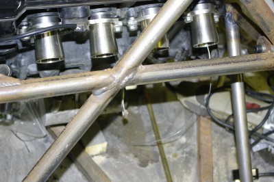
My first idea was to do it on the car. So I mounted up the exhaust headers and began faffing around, but planning something in 3 dimensions is a virtual impossibility, particularly when you’re just modelling something that you don’t actually have in your hands yet.
Inside no 1 outlet on the far right is a small disk of aluminium with a 1.6mm home up the middle the idea was to centralise the aluminium welding rod I had cut to the right length for the primary (you can see it hanging out of the port). The idea was then to bend this to shape using 100mm bends (basically around a tin of filler). But I quickly lost the will to live trying to do it this way… what with the access problems due to all the chassis members around the back of the car, and the tendancy of the rods to wander around all over the place. Life is too short fo this sort of faffing around, there must be an easier way.
After a few moments of pondering I hit on the following.
Step1. Weld a couple of mild steel welding rods together at one end, then measure from the weld and cut the free length of both rods to the magic length supplied by Andy. I deducted the length of the port flanges (60mm) and add a further 10mm to allow for my mock mounting flange. Bend from the welded end to simulate a merge collector, and whatever you are left with is the free length of the primary.
Step 2. Measure the primary separation on the block, and drill a block of wood at these centres with 2mm holes.
 Step 3. Now working at a comfortable height on the bench, fit the joined welding rods to the port centre holes (1 paired with 2 and 3 paired with 4 as is common on superbike engines) , and then manipulate welding rods, by bending in approximate curves to come up with the primary routing.
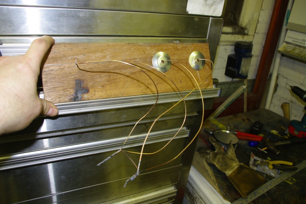
Following my plan I came up with this.
You can see that the merge points for both paired primaries are held together at the correct separation for the secondaries, by a short length of welding rod.
The washers are some 45 mm in diameter, and as the welding rods mark the centre lines of the tube, and are exactly the same length passing the washer along two side by side wires, allows me to check if the wires have the correct separation, to ensure the pipes wont clash. Its a bit like the old fair ground game of passing a loop of wire along a wiggly path… if the wires touch the buzzer sounds.
I think no 1 might need a little more work, but generally I’m pretty happy with this. So I’m going to take my model to AB Performance, to discuss with Andy tomorrow.
Incidentally, contrary to popular belief I’m not actually going mad…. but the starter motor running in the wrong direction in my last post was actually correct. Andy had given me one of the ones he uses on cars with a prop shaft (Like a fisher Fury), these are reverse wound and so spin in the opposite diection. So I’ll get that swapped tomorrow.
