I’ve not got too much done on the Sabre this week, as I’ve been focusing on the mini for a few days (which will be the subject of a separate update) and then just when I was ready to focus on the Sabre again, Kate’s road car shredded its timing belt and bent a valve, so I’ve spent most of this week rebuilding the top end of a Renault Megane engine instead of race car building. With the Megane running again (first turn of the key I might add ![]() ) it was time to get on with the Sabre.
) it was time to get on with the Sabre.
But what I have done is complete the remaining engine mounts, complete the steering, and make a start on the gearshift and the reverse mechanism….. Can you tell I’m running a bit scared of making the exhaust manifold and doing lots of other stuff instead ![]()
 The last major mount to be completed on the engine mounts was the “support” leg of the front left mounting. This needed taking back from the mounting point on the block to the lower chassis rail. Previously I would have put a pair of mounting ears on the transverse tube, and made a complex tube joint on the end of the engine mount. But last time I was over at AB Performance chatting to Andy Bates he suggested I did it with a crush tube and bucket bush instead.
I’ve made so many of these in the last few days, my lathe is covered in a small mountain of swarf. Obviously on the left is the small tube which will form the bush. The small top hat section is welded into the end of the tube. I’ve been asked if washers are good enough and the answer is “No not really.”
 The tall component is the anti crush tube for the chassis rail. The wider section at the bottom sits on one side of the tube, the tall section passes through, and you can see the shoulder on the thin end then supports the inside of the other wall of the box section tube. You then weld in both ends and you’ve successfully tied both sides of the chassis tube together.
In this photo the bush is in the bottom right hand corner, on the end of the triangular right hand mount. As this triangle is pretty acute, I think I’ll put some bracing webs across the engine end.
 I also attacked the rear, upper engine mount, again bucket bushes and spacers were spun up on the lathe. As this joint is very important in preventing the engine and the diff from trying to meet each other when the power comes on, I decided to use the leftovers of the CDS tube I used for the steering column.
The legs aren’t at equal angles because I needed to pick up on the existing anti crush mounts in the transverse chassis tubes. I elected to use the original engine mount bolt, and also I spun down the original aluminium spacer.
With the engine now solidly in place, you can see in this photo I was also doing a trial fit of the engine management loom. The plan is to mount an ali plate on the rear engine mount, and mount the rectifiers here. While I was doing this I also mentally laid out the coolant system.
Unfortunately, the coolant must exit the block to the right, as unlike the Honda CBR1000 engine the thermostat housing cannot be reversed. So unlike the other Sabres mine will have the coolant radiator on the right and the oil on the left.
 With the engine now nailed in place, I can start to think about the ancillary systems that connect to it. The first of these is the gear shift. Andy had provided me with a nice steel splined adapter, and so the first order of business was to weld on an actuating lever. The plan is to use an actuating rod (seen here ) in the engine bay to try and avoid the issues that others have had with push-pull cables overheating and the shift becoming stiff to use. The rod will connect to a push pull cable which will terminate at the firewall. This brings me to the other end of the gear change mechanism… the actuating lever.
 Unfortunately I have RSI/Carpel Tunnel injury in my wrists and this prevents me from using a paddle shift, so I need to fabricate a lever. Now, in the old Genesis I had a habit of breaking the lever, because I’m a bit of an animal with my changes. I also wanted to have a very short throw and that also added additional load to the short welds where the long lever met the pivot tube. So this time around I wanted to avoid a long lever, not least because I’m trying to keep the passenger space clear of moving parts, to allow me to take passengers easily… I have an eager son who wants to get some track time in the Sabre :-).
What this long preamble means, is that I needed to fabricate a pivot point for the lever in the front of the car, after a bit of padding to position me in a comfortable position, we worked out that it needed to be about 6 inches from the main vertical tube. So we started testing it out using the front damper mounts as a makeshift templates. These turned out to be perfectly proportioned. So back to the lathe to knock up some mounting bushes to weld into the vertical tube, and voila we ended up with this.
 The plan is to use a push/pull cable to come up the vertical tube, and connect to a lever attached to the handle. This will then run down to the floor, and then run back to the firewall where it will connect to the activation rod that traverses the engine bay to shift arm.
But of course I can’t use my damper mounts for the gearshift, so I decided to fabricate the pivot mount from mild steel and I used the damper mounts as a template. We often fall in love with shiny shiny aluminium bits, but this 1.6mm steel component is much more rigid and very much lighter than the ali mounts. It needs some reinforcing washers welding onto the main pivot points, but is otherwise complete. I’m just waiting for the push pull cable, and then I can finish this who system off… which would be nice. Its about time I started to get some systems completed, oh and those bolts may be a bit over long ![]()
 Talking of finally finishing stuff, I span down the short steering shaft, and welded it into one of the steering universal joints, to finally finish off the bottom end of the steering column. I used the old trick of dumping the joint itself in water to sink the heat away from the seals and stop the rubbers burning. Once it was all fitted up I ended up with this.
I think My cameras white balance was off BTW. Hence the yellow cast.
I have to admit to spending a couple of minutes spinning the steering wheel, and enjoying the fact that the steering rack moved in and out. At last a mechanism that is working ![]() .
.
 The next thing to report, in this rather long post that is covering a lot of ground, is that I’ve started mounting the reverse system. Andy has provided me with one of the ABPerformance reverse systems, which is basically composed of a geared starter motor, and a specialist drive gear. You can see on the right of this picture that I’ve tacked in a mount at the rear of the engine bay. The tube on the left was intended to connect to the right hand engine mount and the lower tube of the rear engine bay chassis. The plan was to weld a plate on this tube to attach to the free end on the starter motor.
However, I’m having second thoughts as I think a turnbuckle connecting that free hole on the left to the floor will provide a nicely triangulated, adjustable, load bearing mount and save a bit of weight. This will also ensure the reaction forces are transmitted directly to the chassis. But the front edge of this mount will need lateral location and I think the easiest way is to use a small plate to tie the whole thing to the engine, you can see a suitable bolt at the left of the drive gear which is normally used to hold the chain cover on. These chain cover mounts are often pretty weedy, so I’m not using them to hold the whole of the reaction forces, rather just to tie in the motor and stop it jumping away from the sprocket under load. The clothes peg is there to hold the drive pinion out in the operating position, while I trial fit it all.
One odd thing though, I tested the motor by shorting it with my spare battery. Unfortunately, it ran in the opposite direction than required and promptly unscrewed the drive gear from the output shaft with a clunk. When it runs in the correct direction it runs the engine in reverse and tightens the gear on the shaft. I suspect I need a different motor, either that or I’m being stupid.
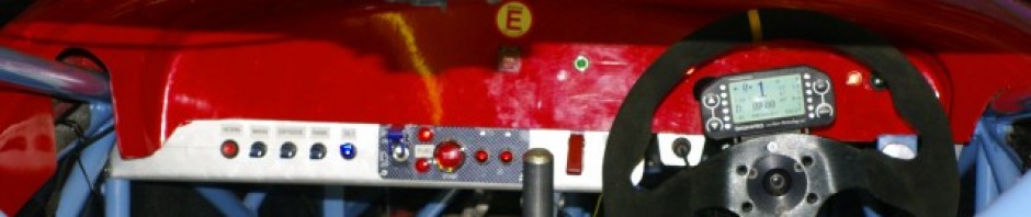
 I’ll be buying the turnbuckle from those nice folks at McGill Motorsport, who today sent me this rather bling switch gear. I bought it from them at the Autosport show, mainly because it was cheaper than buying the switches individually…. you’ve got to admit it is rather bling though!
Oddly those LEDs on the end of the switches are red in real life.
And that just about brings you all up to date.