 As Tim said in his comment two steps forwards then one back, well today I was determined to make decent progress, and take more than 2 forward.
First up- was steering. now that I’ve got the steering mounts sorted out, it was time to attack the rack. Andy had provided me with a brand new 2.4 turn fast rack. He had also provided an empty escort rack casing that had been spun down to fit the steering rack mounts. So it was time. to transfer the internals from one to the other. This isn’t a particularly hard job, but it does require my largest adjustable spanner, which was over in the toolbox in the bus. So after a quick jaunt to fetch it we got on with it.
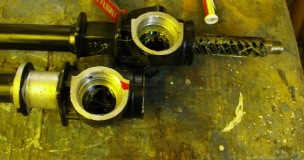
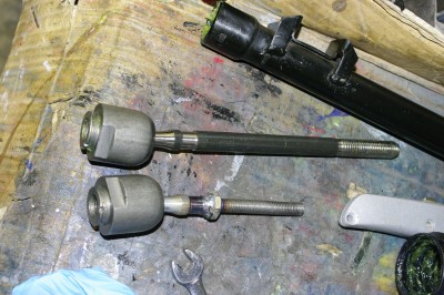 It isn’t a difficult job as you simply remove the shim plate, pull the pinion, remove one of the ball joints and pull the bar. but it does mean you can get at the balljoints, which is a part that requires modification on to fit the Sabre. Basically the standard Escort steering arms are huge and are threaded about 11/16 unf, they are also way too long. I needed to both shorten them and slim them down in the lathe, then cut an m10 thread down the shaft. This did mean I spent the morning on the lathe making yet more swarf.
Because of the difficulty in cutting a thread on the shaft when one end is a balljoint I actually cut 80-90% of the thread on the lathe, and then span an m10x1.5mm die down the partially formed thread to finish it off and clean it up. I also span a nut down to the shoulder and welded it on so that I have an easy toe adjustment point. This is required as the Sabre Steering arms do not rotate, being made of aero tube with a sperical bearing rather than a ball joint at the outboard end. This way I know 1 full term – 1.5mm of toe out.
 Personally I’d have gone for a finer thread say m10x1.0 but the Sabre arms already have 1.5 pitch bosses in them.
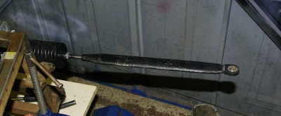
Above you can see the before and after, it did occur to me in the middle of all this that this is still a huge lump of steel, and clearly ripe to be replaced with an aluminium clevis and 3/8 rose joint. That’s a project for the future though.
With both steering arms modified I reassembled the rack and mounted it to the car. At last we’re getting close to having at least one system completed. The only thing left to do on the rack is fit a bronze bush to the non pinion end, I’m waiting on some phosphor bronze bar stock before I can spin one up, and then I can close out the steering rack.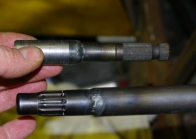
So flushed with success I took my life in my hands, and welded the quick release steering boss to the column…. this I’m glad to report went pleasingly well, although I might shove a 4mm roll pin through the joint just for extra safety.
With the welder out I thought I might as well crack on with the other end of the column. This required sleeving a short splined shaft, welding on an intermediate collar, to step it up to the inside diameter of the column. The shaft is actually welded at both ends.
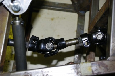 With the rack in place I could finally mock up the intermediate shaft that I”ve worked so hard to get into the steering system. The offset isn’t huge, but it is present, and the installation should be much safer as a result. SoI’m quite pleased, I’m just waiting on another short length of splined shaft and then I can complete the lower end of the steering installation, I can’t cut down the main steering shaft until the pedals are finished as they drive the whole feet, arse, hands, wheel relationships. So best crack on with the Pedals then….
Besides, with temperatures in the garage approaching -4 deg c the thought of being hunched over a hot welder for a couple of hours is pretty attractive.
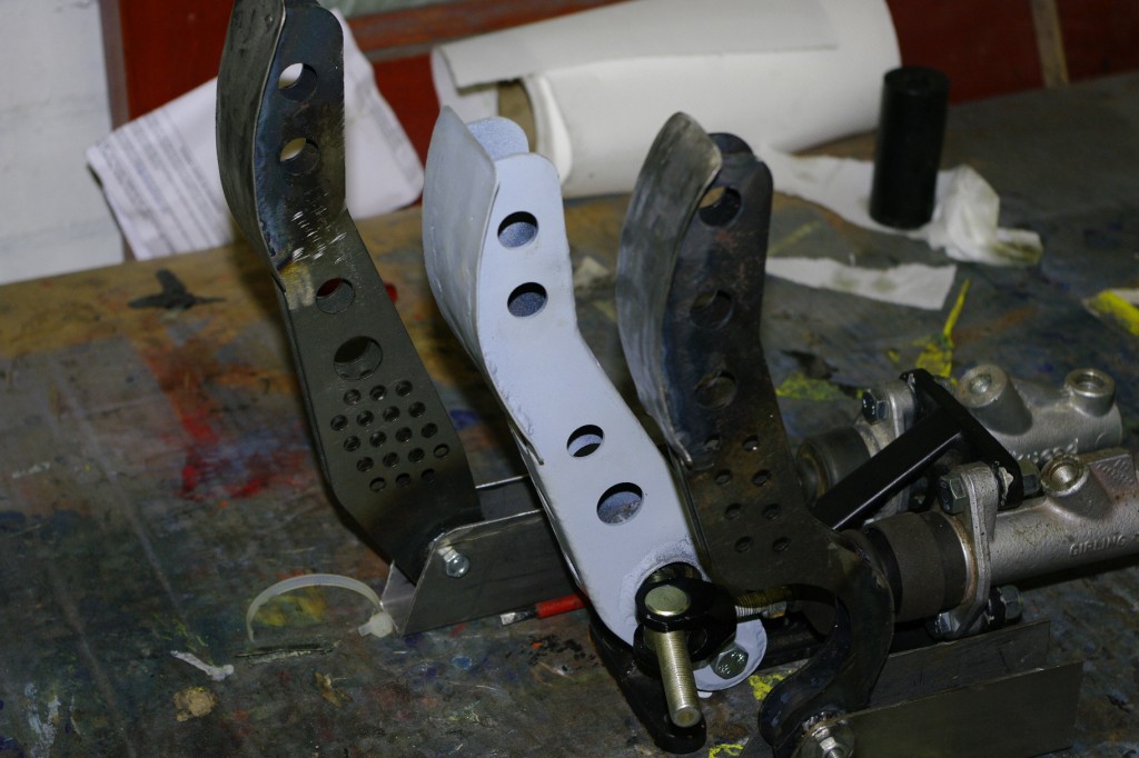
The brake pedal, was done a while ago, so it was time to focus on both the accelerator and clutch…. not much really to show you here except the finished articles. The clutch is sitting on a temporary base which I just knocked up quickly for the photos. Incidentally, the pivots on the clutch and throttle are higher as the brake pedal will be mounted on some 1/2 x 1 inch box, whereas the other pedals will simply be bolted to the 2mm ali floor panel. These aren’t yet complete as they need a return spring, a travel limit screw and the rear rotating quadrants to attach the cables, but they are certainly finished enough to bolt temporarily in the front floor areas and start finalising the ergonomics. Plus I proved to myself that I can still weld ![]() . With that the snow was falling quick and fast, and the home made pizza was calling so I called it a day. But several steps forwards today
. With that the snow was falling quick and fast, and the home made pizza was calling so I called it a day. But several steps forwards today ![]()

