 Oh! you’ve just caught me completing a bit of baking
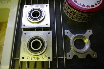
 ![]() . Andy advised that trying to fit the diff bearings by press fitting them alone would likely end in disaster, so the best approach was to use heat and cold. Essentially I stuck the diff bearings (LJ 1-1/2 2RS EU if you’re interested) in the freezer at -18 deg c for 48 hours, and the aluminium housings in the oven at 250 deg c for 30 minutes. Extract both from their thermal lair and the bearings literally just dropped in the housings indeed they dropped so easily they landed with a clang, so the day got off to a great start. After that it went down a hill a bit and I didn’t get as much done as I had hoped.
. Andy advised that trying to fit the diff bearings by press fitting them alone would likely end in disaster, so the best approach was to use heat and cold. Essentially I stuck the diff bearings (LJ 1-1/2 2RS EU if you’re interested) in the freezer at -18 deg c for 48 hours, and the aluminium housings in the oven at 250 deg c for 30 minutes. Extract both from their thermal lair and the bearings literally just dropped in the housings indeed they dropped so easily they landed with a clang, so the day got off to a great start. After that it went down a hill a bit and I didn’t get as much done as I had hoped.
 BTW on the right is the new version which Andy lent me so that I could machine my ones (the ones on the cooling rack) to the new light weight pattern. TBH life’s to short to spend hours unnecessarily spinning the handles of a milling machine, so I shall just buy a couple from Andy later in the build. Apparently they save .75Kg per side. But for now I’m going to use the v1.0 ones to get on with the build.
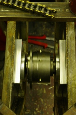
First up, Duncan and I fitted the bearing to the Quaife Diff, using the time honoured method of using a specialist bearing driver and a large hammer. As usual the specified bearing driver was a very large socket that matched the size of the inner race. Once the bearings were properly home on the shoulders of the QDF7ZR, we attempted to fit them to the diff slides at the something back of the Sabre. Hmmm, it seems that something is amis, the combined width of 2 diff mount blocks, 2 sets of bearings and the diff itself was 5 – 6mm wider than the distance between carrier plates in the chassis, further when we measured the front of end the chassis we found the gap tapers by a couple of mm too. So…. we had a cup of tea and a chat. Eventually we re-measured and found that the gap where the diff carriers actually sit was mostly parallel but we still needed to lose 4mm off the combined width. So there was nothing for it but to remove the diff from the carriers, chuck them up in the lathe, and face them back by 2mm each side. But, before I could do the carriers I first had to spin up a proper pusher to allow the bearings to be pulled from the diff. So there then followed a good couple of hours making swarf until finally, after two further trial fitting cycles and a bit more twiddling on the lathe. I had a diff fitted into bearings, bearings fitted into carriers, and the whole lot fitted in the chassis…. yay. :-) some days I wonder why I invested in a lathe. Today was not one of those days.
 Now the reason I started the the job of fitting the diff was actually to start fitting the engine. To do that you need to align the output sprocket with diff sprocket, so obviously having the diff properly mounted is step 1.
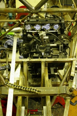
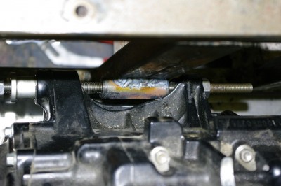
Step 2 is to get the thing in line, and then start fabricating engine mounts. Duncan and I manhandled the zx10 around and eventually worked out it’s rough positioning. With free movement in every plane, its a right pain to get anything set, so we eventually focused on the rear lower gearbox mount. As you can see from the photo below, the gearbox wants to be mounted in free space (don’t they always.)
I have to admit I am slightly concerned that the output sprocket seems to be perilously close to the left hand chassis rail. I’ll need to order a chain wheel, sprocket and chain get them fitted in order to check that out though. I wonder if the slimming down of the bearing blocks has adversely affected the clearance.
So we eventually decided to mount a threaded boss on the upright section of the chassis, in front of the diff carrier. This has the advantage, that you can adjust the left/right alignment of the rear of the engine and hence the output sprocket by using nuts on a long threaded rod, and when happy these can be replaced with permanent spacers of the correct size, and the rod swapped with high tensile bolts.
 The eventual plan is then to fabricate a mount on the “other side”of each gearbox lug, and then the bolts will be in double shear. These will probably go down to the 8mm bosses in the lower chassis rails (you can see the top one in this picture. So more lathe spinning ensued making a threaded boss, which we then flatted on one side and welded into the chassis.
I’ve also completed the brake pedal, it did take a bit of lapping using, a lathe, a broom stick and some grinding paste to remove the high spots from the bearing tube, but otherwise I’m quite pleased with how it has turned out. It looks and feels pretty sturdy, and is only marginally heavier in steel than the original Wilwood aluminium cast pedal. It just now needs a top coat of paint (silver I think) and some grip tape on the pedal section. Here it is in a coat of etch primer.
Now I just need to work out how to mount the clutch and accelerator.
Oh and I’ve also drilled the chassis for the steering mounts, I need to knock up some 8mm bosses to weld in to prevent tube crush, after that I can start work on the steering column proper. So all in all a fair bit of further progress. Still a long way to go though.

