Is it a bloke thing… learning how to weld? Actually its clearly not as those good folks over at The Bluebird project proove, as one of their key volunteers is someone called simply “Girl” who apparently is the best Ali welder on the team. Please support them if you can, their efforts to resurrect Donald Campbell’s hydroplane after 30 years in the mud at the bottom of a lake makes my quest simply to go fast , round and round in circles seem somewhat feeble.
However on with my project in hand, and this is rather a big update I’m afraid. Well since Christmas I’ve mainly been devoting time to to completing the steelwork on the chassis with a view to getting it powder coated before the end of January (though that plan may change). To this end my two tools of choice at the moment are Mr Sparky the angle grinder, and Mr Zappy the Mig Welder.
So far I’ve completed the front foot box, which involved building a whole new floor section, perimeter frame, diagonal bracing and vertical braces. I’ve also cut out the compromised front bulkhead members and replaced with appropriate round section tube and again a diagonal brace . These few words represented some 10 hours of solid work, and the result can be seen below. Everything below the midline in the footwell is new, as is the diagonal brace and round tube in the foreground.

After a day of vibration from welding, cutting, & grinding my carpel tunnels flared up big style to the extent that I spent many hours fighting the dull ache in my wrists and the loss of sensation in my finger tips. To that end taking a rest from the heavy gauge stuff seemed a good idea, so I invested a day over the new year cutting the ZX10 loom into shape. This just simply takes hours, but the only way to do it is to pore over the zx10 circuit diagram, and systematically cut out all the circuits and components you don’t need from the bike loom. The objective is to leave yourself with a dedicated engine management loom, with just a few connections to made to provide power and control via the main car loom. everybody in RGB seems to do this in different ways, but my objectives are.
1) Cut out all the lighting circuits, as these will be controlled by the car.
2) Defeat all the safety interlocks by removing the various diodes and switches in the circuit and identifying which ECU Pins need to be earthed to permanently fool it into to thinking it is safe to start the engine.
3) Remove all the bike switchgear, and transfer only the necessary functions to allow the engine to run properly.
4) Identify the switched and unswitched supply to the ECU, the fuel pump and fan circuits, engine start, engine kill and expose all these as inputs from the main car switch gear and or route to the kill switch appropriately.
5) Remove all non essential ancillary components. Including vehicle down sensor, key switches, fuseboxes, relay boxes etc etc. where necessary defeat or mimic the replaced component if the ECU will throw an error code without it.
6) Identify which circuits and control lines should be sent to the DL1 for logging. Obvious ones are throttle pos, tacho feed, water temp sensor, gear position, airbox pressure, neutral indication and so on.
7) I also retain the clocks signal wires, as the zx10 only displays its fault codes on the clocks as full error codes. Gone are the nice helpful LED flashes that the Honda used instead the ZX10 only issues codes via the clocks… so I’m going to need to get a duff set of clocks of ebay I think.
Tracing every wire in the loom in this way, also helps you check if there are any wires damaged, abraded or generally butchered by the former owners attempt to fit an immobiliser/power commander or other aftermarket device, I’ve got a few of these, particularly around the stick coils so I think the previous owner fitted some sort of performance enhancement gizmo.
After a day at the Kitchen table, tracing wires I ended up with the following piles. On the left is the now minimalist Engine management loom ready for binding, and all nicely labelled up… right is all the stuff I cut out. I’ll post a schematic of this once I can get my paper copy scanned.

I’ve had a few bits of bling arrive. First on the list is a new Dash4Pro and Dl1 mk 3….. which I will use as my primary instruments. Then came a new steering wheel, brake balance bar and brake adjuster from Rally Design. These will get welded into the the pedals outlined in my previous post. Which also incidentally are now with Lasetcut.ltd.uk in Peterborough, who will laser cut me enough for two complete pedal sets (in case I cock one up) for the princely sum of 30 quid.
The steering wheel from Rally Design, will be augmented by a very nice quick release boss from Go-racing.co.uk. And lastly some CDS tube from Merlin for welding in the roll hoop diagonals.
Talking of which… last weekend the new diagonals got cut, welded and fettled in, the added bonus is that they also form an effective headrest, so I don’t need any additional steel for that.
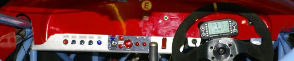
The little bracket on top is for the rainlight that I’ve ordered from www.competitionsupplies.com, and which Chris and I made together last night. and in front of this, is the little welded on tray that holds the DL1 GPS sensor. In this picture you can also see the fitted brake bias control wheel on the dash frame to the right of the steering column. I hope you can also see that the chassis is looking cleaner at the front as I’ve now decided to do pretty much a full build before I get it powder coated and the light surface rust is just annoying me…. so I’ve started wire brushing it off.

The Steering column remains an issue, as I can’t work out its location until I get the push rods fitted. Andy has enough components waiting for me to collect so that I can build up the front right corner…. that will give me the push rod kinematics and from there I’ll know where I can put the steering column. Andy also has a new diff for me which is necessary to arrange engine mounts…. so we are cracking on.
The main wiring diagram is now largely finished too, after a many hours thrashing Visio into submission. Current plan is to use an MTA modular fusebox, with a separate fuse for every circuit, so that the transponder is not killed by a sidelight failure. I’ll be ordering the components and cables for this this week.

The last thing to report tonight is that Chris and I made this little bit of steel tonight. It doesn’t look much but is actually vitally important.


It is in fact the lower half of the support bracket for one of the front suspension mounts. These were incomplete, as the chassis was never finished. As usual I should say that if you buy one from Andy it will all be complete and beautiful, I’m just finishing off one of the prototypes chassis.
So that’s a big update… but I think I’m up to date now.
I have severe progress-envy!
@Tim
Really? I’m actually concerned about the lack of progress if I’m going to be out for Anglesey in August.
See for yourself – http://www.farcester.com
Aiming for Donington. Outsourcing may provide the (fairly normal for me) answer.