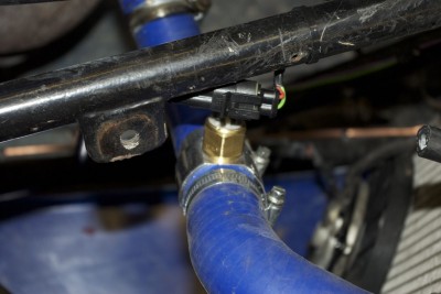
Ok there’s been a fair bit of progress since the last post, following the succesful test of the cooling system last time round I decided that I probably no longer need a manual fan override, and that I should just probably rely on a thermostatic switch to kick the fans in and out at say 80-90 degrees and/or let the ECU control just do its thing. So I ordered a a thermostatic fan switch and hose mounting adapter for fitting it into the top hose. This is because my radiators don’t have a suitable mounting point for one.
So last Saturday I fitted it all up, and tested the system. Despite the fan switch being rated as on 90 deg c and off at 80 deg c. It actually kicked on the fans at 99 and turned them off at 92. Sorry not good enough. I need the beast to maintain 80 degrees on the hottest day on the grid. starting the fans at nearly boil over is no good to anyone.
So I then had to pore over the Intermotor catalog until I found a fan switch with flying leads, a lower temp rating and the correct M16 thread. eventually I found that Part No 50420 fitted the bill nicely. being rated as on at 85 off at 80. THis was duly fitted up and tested, and on this particular switch the tolerance is a bit low, on at 83, and off at 78.
That’s no bad thing and now the car will sit on the drive, all day regulating itself nicely in that temperature range. Phew…. hopefully we’ve finally kicked these cooling problems into touch.
 So onwards onto this weekend. There are few major things left, but the sidepods need finishing off, and I finally need to build a working reverse to meet the MSA regulations. So Dunc did the bodywork and I did the reverse.
About a year ago in a MAchine Mart Sale I bought a small 500KG winch unit. Last year I tried to make the reverse by welding a sprocket onto the end of it and then trying to engage that into the chain. It wasn’t entirely successful, it would move the car if I could keep it engaged in the chain, but generally all it did was bounce around, disengage and chatter against the main chain rollers. Not good.
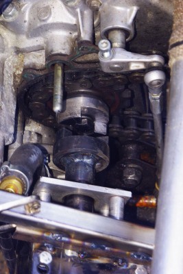
This year I had the idea of making a dog drive unit that mounted directly onto the drive sprocket. Its not unlike Tim‘s as it is basically threaded onto the the bolt, which is then bolted into the output shaft. I owe a debt of thanks to Steve Wiseman (erstwhile RGB racer) who also happens to have a milling machine. So I span up some blanks on my lathe, and then decamped to Steve’s house to use his milling machine to cut the drive dogs. after a couple of hours of hand wheel spinning, I’d completed a set of dogs. You can see one of them mounted on the drive sprocket, and one welded to the driveshaft on the winch. (The fact that the one on the drive shaft is blued, gives you some idea of the heat I had to get into the parts when welding these large lumps of steel) This driveshaft is actually a 17mm socket, and slides on some suitable hex bar to produce a sliding clutch. The hex bar itself is welded onto the output shaft of the winch. The sliding socket has a coller for the actuation mechanism (Which you cant quite see in this picture.
Of course to get this to work the dogs and winch motor have to be axially aligned, and this of course meant that I had to mount the winch in free space, by bolting it to thin air. So there then followed a day of head scratching while we worked out how to build the mounting hardware. But at about 5pm, after much cutting and welding, we were ready to test it. So we jacked up the car manually engaged the dogs and turned on the motor. Well actually we just shorted it to the battery.
Brumm the wheels go around … BACKWARDS! sweeeeet.
Ok lets try it on the ground. Try again.. and yes she moves backwards nicely.
Ok the regs say that it must be able to climb one wheel over a 40mm sqr block. so we tried it first with a 1″ square section of chassis tube under both wheels. spark it off the battery and over she goes. No Trouble. ![]()
Now the big test. I didn’t have a 40mm block, but I did have a 50mm block. lets try that. spark of the battery. bump… up and over she goes. Bloody Hell I’ve built an electric off roader! The only problem we found was that once I killed the juice the car has so much momentum, it carried on moving and because the dogs are radially cut, the opposite side now engage with the stationary winch and this has the effect of undoing the drive dog on the out put shaft. Hopefully once the sliding clutch is spring loaded, the dog will disengage automatically once the load is withdrawn, plus I might chamfer the back side of the dogs so that they get pushed apart by the motion. Even so I’ve never had a working reverse before. I’ll also apply liberal quantities of thread lock to stop it unwinding due to over run loads in normal use. :-).

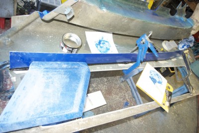
Duncan spent the whole day working on bodywork, firstly he cut, measured and glued in place with some tigerseal the right hand side pod channel roof. This actually sits on the right side pode, and will be held in place on the side channel itself with some nice little slide latches, (Once I find them)
YOu can see that there is a gentle curve on the side pod channel, as it needs to slop upwards to accommodate the full height of the radiator.
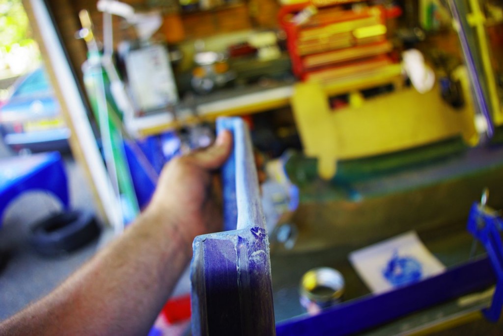
You can also see in this picture the right hand air scoop. While waiting for the tiger seal to go off, Dunc spent a fair bit of time adding filler to the edge of both the left and right hand units. The idea was to build up the edge so that these units have a proper “aero” profile to allow them to work better than just a sharp cut GRP edge would allow. As usual anything that required touch, feel, patience and care Dunc is better at. And anything that need cutting and welding I’m usually first in line for. I do like my new tig welder. Although I am not yet as good as I would like.
Last Job of the day was to fully weld up the previously tacked winch mounts, but lest finish this post with a picture of the baby’s bum smooth aero edge that Duncan took such care to create. Aplogies to my photo Friends for thw lack of depth of field.

