OK, we’re making good progress now, as we move to the end game. First up bodywork. I had picked up the remaining mounting plinth for the right hand side pod last week, and Duncan (and his duff knee) spent most of this Saturday fitting it. Firstly the plinth is mounted to the side pod, and bonded in place with a bunch of divergent rivets and some polyurethane sealant (Tiger seal or CT1). The body itself sits on top of the plinth is mounted with M6 captive nut plates, and some M6 countersunk set screws. Ultimately I’ll probably change these for Dzus fasteners, but for now the screw fasteners will be fine, as I’m not expecting to remove the sidepods very often. Obviously fitting the fibreglass, tends to be a lot more time consuming with a fair amount fit/refit/trim activity and a fair bit of groaning from he of the crocked knee. But Duncan did a sterling job, and I can now report that both sides of the central tub, are complete and fitted, along with the internal shrouding that guides the air through to the oil and water radiators. This is a crucial step as all the other bodywork is keyed off these items. This of course includes the dash\scuttle section, which we can now trim to it’s final size.
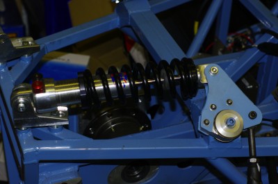
 As for me, I spent most of Saturday finalising the rear suspension. Andy has supplied me with the front and rear roll bars, so I got on with finalising the rear suspension setup. Now you may recall that I had previously mounted up the suspension, and it looked like this. This installation has a number of issues, all of which I’m sure are related to the fact this this is a prototype chassis. It’s not a problem, and exactly was I was expecting. If I tell you that the suspension is on full drop because the car is on jacks , you may start to see the problem. At full droop the motion of the suspension is limited by the maximum damper extension, that’s what stops the wheels falling closer to the ground. So that is the situation here. Now if you look at the bell crank, you can see that relative to the input from the push rod at bottom right of the picture, the bell crank pivot that connects to the damper (The silver bolt at the top of the crank) is already past the centre line of its circle of rotation. This means that as the push rod moves up from the full droop position it has limited travel, before the push rod impacts the silver centre aluminium hub of the bell crank. This will be the upper limit of travel, and is the effective full bump position. In practice you want full bump to be limited by a nice rubber bump stop, which prevent metal on metal contracts. I’m very concerned that this current arrangement would quickly destroy itself, as its motion limits are bits of metal banging into each other.
The positive outcome from this arrangement is that the suspension is rising rate. ie the spring appears to get stiffer as the wheel deflection increases due to the rotation of the bell crank and the relative angles of the motion inputs and outputs…. which is a good and desirable thing as it stops the suspension collapsing under load. But, the arrangement as delivered, limited the overall wheel and damper travel to about 40mm, before it all locked solid. While this is acceptable on a formula 1 car with massive amounts of down force and huge tyres, where much of the springing medium comes from tyre wall squish. It’s not desirable in RGB where we have minimal down force, and the relative weight of the car is low… so the tyre walls don’t get squished too much. In other words rather than using the tyre walls as the major part of the spring medium like F1, I need proper old fashioned suspension that uses the springs, and if I need proper suspension, I need the damper to move through a much larger stroke to control the motion of that suspension. Why? Because dampers work by controlling oil flowing under pressure through an accurately sized orifice or valve and it’s almost impossible to control a very small amount of fluid under high pressure accurately. Think of a garden hose, kink the end so there is no water flowing, if you you turn on the tap and set the pressure high, it is incredibly difficult to release a controlled very small amount of fluid, by controlling the hole size at the exit. Conversely if you set the pressure lower, its much easier to control the flow of a larger amount of fluid over a longer length of flow by simply controlling the orifice size.
What I’m trying to say is short suspension travel, and limited damper movement may be good for a formula style car with slicks and wings… but I don’t think it will work for an RGB car with limited down force. RGB cars rely much more heavily on the mechanical grip of the tyre contact patch, and maintaining the contact patch requires a longer damper stroke so the dampers work correctly, and a longer suspension travel to handle surface changes.
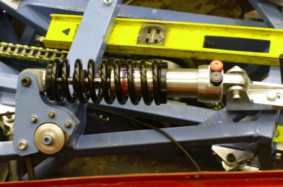
 So after much consultation with Tim, we came up with this arrangement (this is the left rear wheel, above is the right rear version).
The intention is to increase the available damper travel, so the valves work correctly, and also as a consequence gain addition overall suspension movement. Firstly you can see we’ve turned the rear (rightmost) damper mount around to move the damper forwards in the car. You can also see that I’ve pocketed the profile of the bell crank so that it doesn’t foul on the damper body. (this picture was taken at approximate normal ride height rather than full droop), so at full droop the bell crank will rotate at bit further anticlockwise.
Initially we altered the shape with a flap wheel in an angle grinder by trial and error, but once we had the profile, I drew it up in my CAD software, and had the new plates laser cut by Peterborough laser cutting. So I spent some time on Saturday welding up the new bell cranks together, and painting it all. You can now see that even at ride height (which this picture is taken at) the bell crank hasn’t yet got close to the centre line of its rotation. Consequently the damper will use much more of its available length, and the suspension will also have a longer travel. The downside is that we’ve probably traded a little of the rising rate characteristics…. But frankly I’ll trade a little rising rate to ensure I have a viable suspension travel.
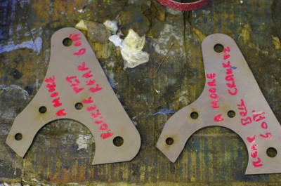
This damper is actually fully installed and all I need to do now at the rear is to fabricate and connect the anti roll bar.  Here you can see the old & new bell crank profiles for the rear suspension. Ialso had some originals made up so that I can recreate the original configuration easily if my modification and reasoning prove false. Remember I ground up the originals to find the appropriate profile so I’ll need some new ones.
The other thing we did, was to insert some 3mm laser cut spacers at the mounting points for the hub (basically cut from the same material, with the same profile and mounting holes as the low left 3 three holes in these side plates. This had the effect of widening the gap, between both sides of the bellcrank, and resolved the problem that I had reported earlier with the dampers binding, as there is now more clearance to allow the damper eye to articulate. Of course with a much wider gap, I had to remake the Top hat spacers that centralise the in the damper and push rod eyes in the bell crank gap, and which convert the 1/2 rose joints on the dampers, and 7/16 ones on the push rod to the 8mm bolts that fit through the holes in the plates.
And that was pretty much my Saturday… fabricate the new bell cranks above from the laser cut components and make endless top hat spacers on the lathe, before I was eventually able to bolt it all together and call it done.
Over the winter I can experiment with alternative bell crank profiles to see if I can recover some of the lost rising rate, while still retaining decent damper and suspension movement… but for now I think I have a workable arrangement for the Birkett.
I should also say thanks to Andy who supplied me with his original drawings so that I could get the bolt hole positioning extremely accurate on the new profiles plates. Incidentally, These issues are to be expected because my chassis is a prototype chassis and therefore different from the production AB Performance Sabres. If you bought one, your suspension would just bolt on, and you’d get brilliant support from Andy throughout the build, as I have done. These issues are simply because this chassis was originally built (we think) for different dampers.

Now on to the front.
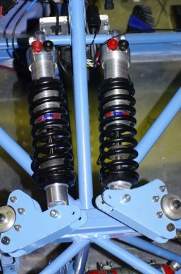
Handily the front dampers are located side by side so its easy to do a direct comparison.
Again this picture is taken at full droop, the new damper arrangements is on the left and the old arrangement is on the right.
Here again I was trying to address the issues of maximise suspension movement before the suspension locks up, and also maximise damper movement so the valves work better.
After my long winded preamble above, I won’t cover the same old ground, but in the new arrangement you can see the bell crank is again rotated away from the damper to increase the available articulation of the system and hence increase available motion. You can see the pockets in the new damper, and if you squint closely you can see that the bell crank is also much thicker due to two of the 3mm spacers I mentioned earlier.
Pro Tec have also supplied me with some extended mounting eyes to allow the LH damper to have a longer reach (but not a longer stroke), so that it could reach the rotated bell crank with out the necessity of cutting out the mounting points near the adjusters at the top of the picture and re fabricating them.
Incidentally, rotating the bell crank doesn’t affect the ride height, because one of the beauties of push rod suspension is that ride height is controlled by the length of the push push rod, not by the position of the bell crank or spring preload. And the push rod is made easily adjustable as it is one long turn buckle, with a LH and RH rose joint at each end, so simply releasing the locknuts and rotating the pushrod changes ride height and corner weighting, and in this case also compensates for the bell crank being rotated (assuming you don’t run out of adjust-ability on the push rod)
With push rods suspension.. The push rods control ride height and corner weight, the bell cranks control suspension rate characteristics and the suspension ratio (how much the damper moves for each mm of suspension movement) and the springs control suspension frequency, as well as the overall behaviour under load. Finally the dampers have separate controls for controlling wheel motion in bump (the black adjuster) and rebound (the red one).
Obviously there are a vast number of adjustments to get to grips with here, and it contrasts starkly with my old car which basically had three adjustments only. Change the springs, wind the spring base up or down or a single knob on the damper that controlled both bump and rebound in a fixed relationship.
I’m clearly in for a bit of a learning curve in setting this car up. Those first few hours testing are going to be fun!
So last major bits of the suspension are to build up the right hand front bell crank, and build both ends ARBS. Then the suspension is done or at least ready for setup. I’ve still not quite got enough travel on the front, so I might get a yet longer mounting eye from Pro Tec for the dampers.
