 Lots of small jobs make this week’s post less than riveting I’m afraid. But they are all on the route to making this beast drivable.
Firstly, I’ve replaced all those silicone bends in the coolant system with some bespoke bent ali pipes that Duncan and I knocked up last weekend. The pipe bending went fairly well considering we were learning to use a new machine, in that we only threw away two versions that we screwed up. Unfortunately, it meant that I couldn’t mount the reverse motor at all. When we came to complete that corner of the engine bay it transpired that the new battery, which I’d installed after deciding to ditch the ultra light but ineffective lithium one, sat about 10mm higher and clashed with the reverse mechanism. Dammit!
So we had to remake the battery mounting tray and all the large current battery cables, which dispatched the complete morning. Once we’d finished we did have a perfectly serviceable installation, although its very tight in that corner. However, there is an air gap between every component, and especially between the hot coolant pipes and the fuel tank. You’ll also see that I’ve also added a 50amp red Anderson connector, which will serve both as a battery charge point, and an emergency connection for my axillary ”jump” battery. Just in case the main battery has a problem mid weekend, as I’ll have to remove the entire coolant system if I need to change it it.
In this picture you can also one of the left side pod stays that Duncan also knocked up, and the car now has both side floors fitted, along with both clamshells which close out the cockpit, and suddenly it is looking much more “car like”.
 Now, in the last post, you may recall that I had a problem with oil pressure readings. The existing sensor unit was doing some really weird stuff. In the various sessions of coolant system testing I’d even observed the oil pressure increasing as the oil temperature increased which is basically against the laws of physics, as raised temperature makes the oil thinner. So eventually I decided to swap out the ETB instruments sensor for the Race Technology one. Unfortunately this required more than just a sensor change as I also had to change the wiring. The race technology sensor is a three wire sensor, whereas the ETB one is a single wire one.
Here you can see the sensors installed with the original bike low pressure switch attached to a T piece. The great thing about the RT sensor is that it is pre calibrated within the software. Once it was all re-configured, it all seemed pretty good until I did the main oil pressure test , which should give 28-35Psi at 400 revs with the oil at 80 degrees. Unfortunately I could only get 25. Hmmm
So I decided to check it even further, and installed my analog dial type fuel pressure gauge in the T Piece. Then I had a brain wave, despite me choosing the PSI variable in the config software, it wouldn’t be beyond the realms of possibility that it was displaying BAR without the decimal point, a quick calculation (multiply bar by 14 to get PSI) seemed the indicate it was plausible. So I went ahead and manually entered the PSI formula, then re flashed the Dash4Pro display.
Hurrah success!… The analog gauge and the digital system were in perfect lockstep as I wound up the revs to the necessary 4000 rpm, and I got the perfect values when I did the 4000rpm test. When The engine is cold I get 32-34 PSI at idle and when the oil temp is in the 80-90s I get about 4 PSI. All of which aligns with my mates Tony and Bob, who both run ZX10s in RGB and with Andy Bate’s experience. One way to improve pressure is to run 15w40 oil, rather than the 10w40 I usually run…. but at least I know that I’ve got main bearings in good condition and I can trust the displayed values on the dash. Excellent.

Next on the list was installation of the drive train. Andy is awaiting some driveshafts from GKN, but not withstanding this last link in the drive train, She’s pretty much ready to go.
Firstly I had to remove the reverse motor sprocket, as I needed to file down and extend the spanner flats on it to allow me to get my largest ever spanner (34mm) onto it so that I could tighten it in the increasingly congested engine bay. This happened easily enough, once I’d broken the grip of the threadlock holding it on.
Once that was off I swapped the front sprocket to a 17 point one. Tony Gaunt suggested the optimal choice for the zx10 for most tracks was a 17 front and 52 point rear. Which, after I had fitted the reverse gear again (more threadlock) meant I was ready to fit the rear sprocket.
As always I use 530 sigma DID x-ring chain, and the chain in this car is 101 links long…. which is usefully just short of the 102 links of a standard size, so I only have one link to remove, and I’m not throwing away cash. As always I get all my sprockets from B&C express, who know the bolt patterns and clearances for the Quaife ATB Diff (QDF7ZR), and who also supplied the chain and a natty little 60 quid chain break tool that works extremely well to remove the unwanted link. Much better than the bash it (and your knuckles) with a hammer type I already have. While doing all this I pumped the Diff full of grease too.
Of course I also needed to cut the sprocket in half so that it will be easy to change without demounting the diff… this is just a tedious exercise in accurate hack sawing. The sprocket is mounted using 50mm 12.8 grade Cap head bolts, cut down to 32mm and fitted with M10 K nuts and nordlock washers, I use over long bolts because that gives me an untreaded shank through the holes for extra strength. This is desirable as essentially all the power of the engine goes through the shanks of these 8 bolts acting in shear. So extra strength is good ![]() . So that’s the drive train installed, bar the tension devices,,, which are just a couple of threaded rods and nuts and those GKN driveshafts.
. So that’s the drive train installed, bar the tension devices,,, which are just a couple of threaded rods and nuts and those GKN driveshafts.
Duncan spent a couple of hours making a heat shield and support for the exhaust can… and then finally we got on to a job that’s I’ve been dreading. Making the clutch pedal.
 The reason I’ve been dreading this is that I’d originally planned, an arrangement that brought the clutch cable in to the pedal from above, so that I kept the cable away from my feet…. I want both the passenger and driver foot wells to be as clear a possible. We’ve since decided that this is way over complex and the KISS principle should apply. Hence the way to go is to bring the clutch cable along side my left foot to a hard mount for the outer, and then actuate the inner cable with a simple stand off from the pedal.
This simple little description covers about 90 minutes worth of measuring, faffing and fabricating. All of it, of course, down by my feet, so it definitely took both of us.
The result was this natty little bracket which we will rivnut into place. If you look carefully you can see a little angled threaded bush holding the cable outer, is carefully angles down and away from my feet. This I knocked up on the lathe and then TIGged it onto that piece of angle which was hewn from some 2 x 1 box section. Of course it would have been better to weld this all to the chassis before we powder coated it… but as they say ” hindsight is an exact science.”
With that, we ran out time on Saturday, but I just now need to paint and fit this widget, and fit a return stop to stop the pedal falling towards me. Looking at the strain on the pedal sides I also need to make a bigger centre spacer for the actuating arm. But the monster of a job that has been sitting on my to-do list for a while has been slain …. yay ![]()
Oh and does it clear my feet? yes of course it does. The angle of the cable and the bracket is carefully set to match the rest angle that my left foot forms when my heels are on the support bar….. I don’t even known the cable is there. Which is great.
After Saturday tea, I festooned the kitchen table with wire, shrink wrap, cable ties and other paraphernalia so I could get on with the main dashboard.

After much clipping, soldering and shrinkwrapping I ended up with this.
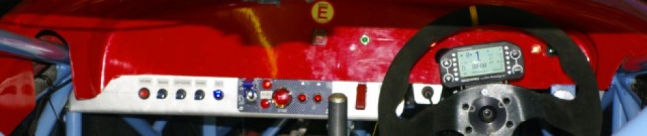
The two ultra bright RED LEDs are dual oil warning lights. The greens are indicators (and are slightly larger than the LED I would have used because I (Cough) drilled the holes in the wrong place. The green light is neutral indicator, and the red square push butting under a protective shutter is the fire extinguisher trigger. It’s all nice, neat, and minimalist as most of the instruments are on the DASH4PRO. Incidentally the holes are for the previous owner’s paddle shift actuating rods…. which I won’t be using so they will be covered with a little Ali plate.
Just for Tim here’s a shot of the back so he can verify my wiring is up to scratch.
