I’ve much progress to report again today. Which is a good thing, as while I’ve missed my target of being at the Anglesey meeting in Mid August, I do not want to miss the Birkett at the end of October.
I’ve now hung all the suspension, so the car has been rolled out of the garage, but this will take a full blog post on its own to cover and I need to revisit my notes to ensure it makes sense, so right now I’m going to focus on two other major milestone systems which we’ve completed this weekend.
 We’ve finished all the components of the engine bay installation and had her running
 ![]() , and I also have most of a complete braking system. We do seem to be accelerating towards completion at the moment.
, and I also have most of a complete braking system. We do seem to be accelerating towards completion at the moment. ![]()
Firstly lets talk about the cooling system. This is arguably complete, it’s certainly water tight, cooling the engine and has been pressure tested. But I currently regard it as a “mock up” as its got far too many individual bends in it linked by short aluminium tube joints. To build it took 19 jubilee clips which is far, far too many potential failure points. The jubilee clips are a bit oversized anyway so I want to change them.
So I’ll be replacing most of these silicone bends with single lengths of 1″ aluminium tube bent to the correct shape. I would have done it this way first, but the tool I’d ordered to do the job failed to turn up in time. So I decided to mock it up, using silicone, and Tim kindly lent me a few spare elbows that he’d collected over the years to enable me to complete and test the system… that’s why the elbow in this view appears to have a redundant take off. It’s because its one of those borrowed bends which will be replaced shortly. The radiator is a double pass 400mm fully aluminium radiator that I got from ebay. The outlets are 32mm , and its also got a little air bleed on the top right, to bleed air from the rad back to the header tank. Its designed for a MK1/2 Golf Gti/Scirocco 1.6 1.8 8v (1986-1992). The radiator is mounted on a little top hat section which I made, which both raises it to the height of the aperture in the bodywork, and also usefully stiffens the left hand side pod floor. The rad is also fitted with 4 mounting bosses on both sides, which are handy for attaching mounting hardware too. The fan, itself is a standard 2010 zx10 fan, mounted on rivnuts in the top hat section, and a little bracket mounted on the top shroud of the rad.

This picture, basically shows all the rest of the system.
The black hose passing from the top left hand corner, under the tank, and then joining via a short aluminium section to the blue bends at the bottom of the picture is the hot top hose from the cylinder head outlet. It flows continually down hill to the rad, and this would normally cause a problem, because any air bubble would collect in the thermostat housing/head and cause and airlock, with the inevitable overheating problems. But, if you look in the top right hand corner you can see a pair of mole grip crimping a small pipe. This is the airbleed from the very top of the cylinder head, for this mockup we just bled the excess air out of the system and then crimped the hose with some mole grips, In the final installation this will connect to the bleed nozzle on the lower left of the header tank, where it will meet the blue hose (the bleed from the top of the rad) at a T union. This is an inverted loop, so any trapped air should rise up to the header tank via the T junction, it also allows the system to be filled from the lowest points, which also helps prevent airlocks.
The cold feed comes from the bottom of the rad up to a T junction, which allows connection via a 90 degree elbow or two to the header tank. It then dives down again to the upward angled inlet on the standard water
The only other two bits of the system are a small cap plug on the 10mm outlet on the water pump outlook which would normally feed the oil to water cooler on the back of the engine (which I’ve removed), and the standard block hose which feeds the water pump outlet to the head inlet.
The intention was to keep the system neat and simple, to retain a clear expansion tank, as this is both cheap and enables very quick level checking. And most importantly of all, to try and make the system self bleeding, to avoid air locks, which have been a serious problem on previous engines.
Once we’d got the system together, and checked it twice, we filled it up with plain old tapwater to test it. We then pushed the car out of the garage, powered her up, did a few last checks and hit the start button.
She growled into life at first thumb of the button… which was nice. And we just sat and watched her… correcting a solitary leak, and checking now and then for oil leaks or other issues. She was a bit noisy as the PAIR valves aren’t currently connected, but it pretty uneventful (WHICH IS GREAT ![]() ). The temperature rose gently to about 95 degrees and then the fan cut in, and the temperature then dropped slowly until the fan cut out again, which is the normal thermal hysterisis and means the Fan is correctly sized. We let her warm up again, and then killed the ignition with the fan running. Turning the ignition back on, restarted the fan, without starting the engine. Again this is great, as the ECU will control the fan even if the engine is not running, so I can bring a hot car back to paddock, kill the engine, and then leave it sitting for a couple of minutes to help cool the engine. Of course I’ll be relying on circulation by convection, as the pump is mechanically driven by the engine, but as that is powerful enough to drive the earth’s techtonic plates… it may also work well here. If not, I’ve got a very small bypass pump I can fit if necessary, but at this stage I’d like tot try and keep the plumbing really simple.
). The temperature rose gently to about 95 degrees and then the fan cut in, and the temperature then dropped slowly until the fan cut out again, which is the normal thermal hysterisis and means the Fan is correctly sized. We let her warm up again, and then killed the ignition with the fan running. Turning the ignition back on, restarted the fan, without starting the engine. Again this is great, as the ECU will control the fan even if the engine is not running, so I can bring a hot car back to paddock, kill the engine, and then leave it sitting for a couple of minutes to help cool the engine. Of course I’ll be relying on circulation by convection, as the pump is mechanically driven by the engine, but as that is powerful enough to drive the earth’s techtonic plates… it may also work well here. If not, I’ve got a very small bypass pump I can fit if necessary, but at this stage I’d like tot try and keep the plumbing really simple.
I will replace all those bends with purpose bent Ali tubing once my new tube bending machine arrives.
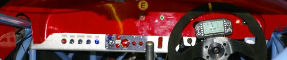
One odd thing did happen, as the engine heated up, the oil pressure dropped and dropped until it was showing an indicated zero. I wasn’t too bothered about the particular number displayed on the Dash4 Pro as this is most likely a calibration/sensor error, but it is certainly something that I want to investigate further, because I really need to trust the oil pressure numbers.

So onto the brakes. These have proven a little more problematical than I would have liked, basically there is not much clearance at all, even with the spacers I mentioned in the previous post the wheel rotates but does just drag on the inside of the rim, periodically. There is about 5mm of clearance between the edge of the disk and the inside of the calliper so the obvious thing to do is mount the Powerlight callipers further towards the centre of the wheel, so that the outer edge doesn’t rub on the rim, but still to maintain the necessary disk/caliper clearance.
The mounting brackets, have fair bit of clearance so the obvious thing is to machine back the lands where the caliper sits. fortunately I know a mate in CAM7 who has a manual milling machine. So a quick hour spent at Steve W’s house (you can see the machining at the ends of these brackets) meant that I had some significantly thinned down brackets (about 2mm) which now mean that the callipers fit inside the wheels. Or they would have done if the threads hadn’t stripped out of this mounting bracket… I guess that means I’ll be learning how to helicoil the damaged threads then.
Magic .. but don’t let up as the “finishing up little things” are going to slow you down …. I went through the same thing on coolant plumbing and in the end decided to do without Al pipes & Bends almost completely for the same reason you quote .. to minimise joints. So I went with almost all hose and eliminated loads of jubilee clips. Keep pushing
Colin
Cheers, we are getting there but I’m starting to feel the pressure of the Birkett breathing down my neck… I am running out of systems to complete now. I’m hoping three to four weeks will see it completed, which should allow some testing before the Birkett.