
Well its been about a month since my last post, but despite my tardyness on digital reporting, I’ve not been idle. I’ve been steadily driving forward towards to the magic moment when the beast bursts into life. You may recall that I’d taken delivery of the bodywork, and that this allowed my to finalise the exhaust position. Basically this involved orientating the last bend into the can, cutting it and welding it on to the end cap, so that the other end of the exhaust exits through the pre-existing hole in the side pod.
After that I drilled the joint and welded on the Lambda sensor boss. All of this takes a lot less time to describe than it does to to do of course and completing the exhaust represents about a full weekends work. The Y piece is also adorned with a couple of eyelets for the tension hooks that hold the whole thing together, obviously there are matching pairs across each joint a total of 6 springs all together.
 Those little M5 Cap head bolts around perimeter of the can are to allow me to disassemble it, and re pack it… which is an all to frequent practice.
At the other end of the Can is a slip joint, which I’ve welded into the end cap, The slip joint is to allow me to fit the MSA Mandated Catalytic converter, which I’ve cut from the original exhaust that came with the zx10. This is currently over long and I’ll trim it back to a much thinner slice of cat once I have the bodywork in place to get the line. The idea of the slip joint, is so that when I don’t need the cat I can simply pull it from the Can and replace it with a standard exit tube. If you look carefully at this pic, you might also see that the far edge is not circular as I’ve cut it back to clear the bodywork, and there is essentially a segment of the circumference missing and capped with a flat plate. With the addition of some heat wrap to the headers and few minutes struggling to get at the bolts, the exhaust system fabrication is complete, although I think I’ll also wrap the remaining merge collector too.

Now, if you look at the photo you can see some high pressure oil pipes, traversing each side of the exhaust…. these obviously need to connect to something, and of course that is the oiler cooler.

Here it is sitting on the new floor that I made from the templates Andy supplied…. You can see it is currently making a handy shelf ![]() .
.
The floor is made from 1.6mm T6 tempered aluminium which I bought as an 1.2 x2.4 m sheet. And I have to say it is very tough stuff, particularly as it broke my favourite air nibbler.
The cooler itself is a heavy duty unit, as RGB experience is that these are less susceptible to the stress fractures, that cause leaks and blown engines. It sits on a small plinth that lifts it up to the correct height for the duct in the bodywork. If you’re interested in the details, it is a 25 row, 235mm matrix with dash 10 AN/JIC fittings.
The neat little plinth, plus the stabilising bracket on the left, made from an off cut of that indestructible side pod floor, are of course the work of sheet metal master Duncan. BTW for all my RGB mates who’ve asked about his crocked knee… the MRI scan shows inoperable patella cartilaginous damage… but it is improving with the help of a petite & pretty physiotherapist… which I’m sure would help most conditions ![]() .
.
So all that remained to complete the oil system was to fit the oil temp sensor that doubled as a sump plug, unfortunately this wasn’t as easy as I’d hoped as the sensor used an M12 x 1.5 thread, and the sump has a M12 x1.7 port. 0.25 makes all the difference.

By now I’d completed all the rest of the system, so I didn’t want to tear it apart again at the front of the engine to make a temp sensor port, so my only option was to make a widget.
Now I occasionally get asked questions like, “Why do you do the racing lark, its expensive, time consuming and you don’t win anything”.
Well the reasons are many-fold, it is something to do on my Saturdays, I love being in the paddock with my buddies, it forces me to test and stretch my Myself in the car and I lean new skills of all types… BUT… its also about the pride in making something with your own hands, and nothing embodies that better than making a widget.
This little bit of steel ( Not aluminium or brass because they crack and fail) has an M12 x1.75 male thread on one end to go in the sump, and an M12 x1.5 female port on the other to take the sensor, and a hole up the middle to let the oil bathe the sensor. I made this out of a solid piece of hex bar. I used my hands and eyes, and 10 tools. (lathe, M12 tap, M12 tap handle, M12 die, M12 die handle, centre drill and 5 .5mm drill, and Hacksaw, fine file and vice ).
It was conceived in my mind, and made real by my hands… and it fitted perfectly into the parts made super accurately, by computer driven machines. There a certain pride to be derived from making something really well, even if it will be buried at the bottom of the engine bay and hardly ever seen again. That’s the satisfaction and glory of the widget!
Anyway it fitted perfectly, and I’ve wound it into the sump port, and locked it in place with an appropriately place jubillee clip.
So the oil system, and exhaust systems are complete…..Excellent, what’s next?
 Well I need to test this engine and actually get it running, the only things I now need to do before I can hit the start button is to fill it with oil, and make sure the electrics are complete. It doesn’t have a coolant system yet…. but I can run it for a brief period using just the oil alone to cool it.
The ignition circuits have been complete for a while, but I did spend a few hours giving the dash wiring a final clean up. One thing I did need to do was to mount the regulator, and complete its connections. These cables aren’t yet properly tied down… but the wiring is complete.
So with the oil circuit complete, the necessary engine management cabling complete, and the alternator properly plumbed in…. I’d run out of excuses. It was time.
I filled the engine with oil, and as both the oil cooler and new filter were empty, I manually filled the cooler before fitting the hoses. Then in the time honoured tradition I removed the plugs and span the starter on the battery to get some oil pressure. This illuminated the first problem…. the ultralight lithium battery goes flat pretty quickly if the engine doesn’t start at the first turn of the key. So I’ve decided to replace it with the normal lead acid type and (at least initially) take the hit in weight for improved starting reliability. I jumpered in a support battery and continued cranking until I got pressure, then I refitted the plugs and stick coils.
Now there really are no excuses!
First lob in a few litres of unleaded fuel, connect the fuel pump, and run the ignition cycle a few times to charge the fuel rail. Check for leaks… we’re ok? Then hit the start button.
There followed a few minutes of coughing and non starting, as I think, the injectors got charged, and re lubed by the fuel, then she fired, at first running on a couple of cylinders, then 3 and four kicked in and she ran properly. Once running each restart was much less hassle, but without a cooling system I couldn’t let her do much more than run for 30 seconds each time. BUT she is running, and that means that I’ve manged to get every one of the 1000 things in the critical path to this point done correctly.
A major milestone has been reached, and I pronounce my self ”Most well chuffed”. So chuffed in fact that I rang Dunc and Tim to let them hear my engine running for the first time. They must think I’m a nutter.
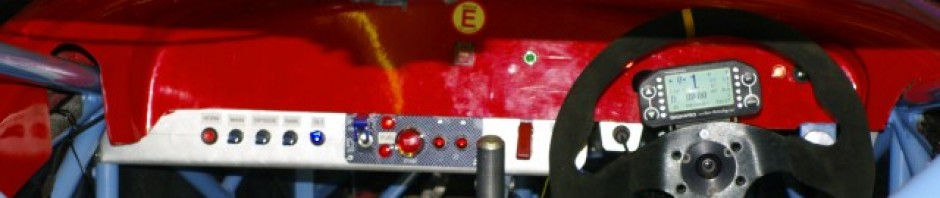
Anyway by way of proof here’s a shot of the Dash4 Pro. In the top right corner where it says 1302…. that’s the engine RPM.

You may want to consider passing some threaded bar and spacers all the way through to the oil cooler top mounting points, a few coolers have sprung a leak when only mounted on the one face.