Right, I’m beginning to feel that I’m on the home run with this car now. However I’m still very jumpy about making the meeting @ Anglesey in early August. Unfortunately, my loyal Chief Pit Monkey, Duncan has monumentally crocked his knee, and is hobbling around on crutches pretty much unable to do much. Given that my garage is basically a large collection of trip hazards, he spent most of Saturday perched on a stack of tyres. He’s still fulfilling his very useful function of bouncing ideas around, but in terms of tool wielding he’s operating at <3% normal function poor chap. It’s looking like he may not be driving again until Christmas, which for an avowed Petrol Head like Dunc…. is torture.
So get well soon mate.
So what did we get done?
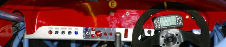
 First up I spun up some little end pieces of hex bar on the lathe. These were fitted to a section of connecting rod and were tapped M5 at one end to fit the gear shift push/pull cable, and M6 Left hand at the other end, for a rose joint to connect to the gear change lever. This essentially makes a large turn buckle, which allows me to fine tune the angle of the gear shift lever. So I connected it all together, and yanked on the lever. It all worked as expected… not least because this was the second one I’d made. However the Dash4Pro did nicely show “-” or “1″ as I worked it between neutral and first. Its always very nice when the differnet systems start becoming self reinforcing.
 ![]() Incidentally the red cable in the front is the main power feed between the reverse and start relays. And Looking at that picture I need to remember to put a bolt in the shift arm.
Incidentally the red cable in the front is the main power feed between the reverse and start relays. And Looking at that picture I need to remember to put a bolt in the shift arm.
 While at the lathe I also spun up some little “pushers” for the diff adjuster. They are the cylindrical objects on the left end of the threaded section.
They are supposed to engage with the m12 cap bolt you can see at the top of the picture ( the diff bearing carrier is rotated 90 degrees anticlockwise from its normal position.) The bolt providing a hard point for the pusher to engage with and apply tension to the chain. The position of the pusher is then locked using nuts either side of the locating tube in the chassis.
However we have a problem, you may recall I had to thin down the bearing mounts to get the diff to fit in the chassis. This has had the effect of moving the centre line of the cap bolt away from the centre line of the mounting tube, so that the little locating lug I’d placed on the pusher no longer engages without undue side load. Duncan dispensed a plan from his throne of tyres, which means we’ll fit a steel plate, with an off center cap either welded to it, or simply just a hole drilled in it to locate the pusher. But I’ve just not got around to it yet.
 Now, the rather poor Meatloaf reference in the title of the post is referring to the pedals. Since I originally fitted the brake pedals I’d been unhappy that the correct pedal position couldn’t be obtained as the master cylinder pushrods were too short. So I spent a couple of hours disassembling the entire assembly refitting the pushrods, and Master cylinders on the other side of the frame, and then relocating the whole frame further forwards to get the correct pedal angles. This is a right pain in the backside as all of the bolts are perilously close to each other, and it all has to be done in the correct order. However when it was done, it gave me the correct pedal angles, and a good reference for positioning the throttle, so I could get on with that. I’d made the pedal ages ago, but now needed to fabricate the mount, including the pull cable connection, the mounting base, and the all important secondary return spring which is mandated by the Blue book.
I did have a grand plan for a rotating quadrant, to give me tunable throttle response, but I’ve essentially decided to Keep it simple and just use a direct throttle pull. You can see this sticking out to the right, made out of hex bar. The little grey unit in the right chassis rail is the cable pull mount, again spun up on the lathe, and you can also see the return spring wrapped around the pivot point. However overall, I’m very pleased that I’ve kept the floor area clean of cables and the like as I hate stuff under my feet.
This all took a surprising long time to locate and position as it’s difficult to see how everything is positioned, you want it in line, and close enough to the brake pedal so you can heel and toe when the brakes are actuated, but no so close that you catch the throttle when hitting the brakes.
This also means that the throttle needs to be set back a bit so it can be hit by the heel-toe, when the brake pedal is active and therefore partiallydepressed.
Of course this is also hard when the brakes aren’t complete, so the system isn’t pressurised and the pedal can go straight to the bulkhead.
This side view also shows the reason for the swan neck on the throttle pedal, in that it needs to clear the adjusting cable on the bias adjuster.
You can slo see the little Ali adjustable travel stop I made and fitted to the chassis rail.
I’m just waiting on a cable to be delivered and I can complete the throttle assembly. Then I need to do the same for the clutch, which promises to be a fair bit more tricky.