A couple of days ago , I flipped the ignition switch and the fuel pump relay went click, the secondary throttle servo motor went whirr and the exhaust valve twiddled a bit, then the pump light went off. YES YES YES!… That means that the ECU is alive, there was no smoke or fuss. It just did the right things. This was cause for much celebration… or at least a bottle of beer. However, I must backtrack a bit, as there have been many steps along the way from the state of the car in my last post…. you might want to grab a cup of tea.
 Ok. In the last post the engine was properly nailed in, this meant that I could start getting on with the ECU wiring loom. I’d spent a few hours poring over this previously, but now with it laid across the engine it was immediately apparent that it as way too long, and needed about 8″ cut out of 50 odd cables. I cogitated over this for a while, as I was injecting a failure point in each cable, in the hope of saving a few hundred grammes of unwanted cable… but in the end I persevered and just got on with it. It took nearly a whole day to sort it out.
Incidentally, Duncan knocked up the little ali plate that the ECU is mounted on, it also holds the exhaust Gas valve, and will also have the power commander velcroed on top of the EGV. This also makes the ECU visible which is a requirement of the 2012 RGB regs. Once I’d finished shortening the main loom, I also had to collect together all the engine earths, and the interlock cables, and take them to chassis earth.
The loom takes 6 connections from the main car. These are fuel pump control, power to injectors, power to stick coils, ECU switched power supply, start sense, and fan relay control. These all ended up in 6 way waterproof connector, awaiting interface with the as yet non existent car loom.
The other things to pull out of the ECU loom are throttle position, tacho feed, oil pressure warning, oil temp sensor, oil pressure sensor, gear position indicator, neutral indicator & coolant temp lines. The majority of these would have ended up in the original bike’s clocks, and in the racer they will either go to the data logger or to dash warning LEDS. Again these all exited to water proof connectors. I also retained the feed cables for the bike clocks . I intend to acquire a bashed up set when one appears on ebay, as unfortunately Mr Kawasaki has abandoned the eminently sensible idea of reading the ecu error codes from a flashing light, but has instead opted for an ultra modern display of the codes on the clocks in ASCII format. Easier to read I suppose for the novice… but it does mean I need the £100 clocks to read the diagnostics in the paddock rather than a 50p LED
After much faffing around I finally managed to get the loom in decent shape. The last two things to add were the 100 ohm resister which is necessary to override the simplistic immobiliser system on this American engine, and to build a 22K/100K potential divider from a couple of resisters which is necessary to allow me to remove the vehicle down sensor from the loom. An alternative approach if you’re not confident with electronics is to simply position the sensor upright, and fill it full of epoxy.
 So with the engine , both nailed in and (fingers crossed) electrically complete, I needed to work on the rest of the car loom, this of course is built around the three main components, the CARTEK isolation system, battery and main power relays in the engine bay. The dashboard and the main fuse box. So I’ve spent most of the last couple of weeks worth of evenings building the dash, and running cables around the car. This is a long dull process, but I can now happily report that the car is electrically complete bar those bits such as lighting looms which reside on the bodywork (which I don’t yet have). That is .. all the lighting circuits are in, the dash control switch gear , the power switch and warning looms are in. The fuel pump and fan control looms are complete, and I’ve run all the interconnects to the engine, and all the wires to the data logger, rain light, transponder and wide band lambda sensor. The engine bay sensors and warning lights are fitted and operational.
I’ve even mounted the instruments…. or rather the instrument, as I’m using just one display unit, the Race-Technology Dash4Pro. I’m now at the tidy up and tie down stage of finalising the looms but I can’t do that until I get the side body panels.
 I’ve opted to use the Race-technology Dash4 Pro…. and I really can’t speak highly enough of Race Technology http://www.race-technology.co.uk, as they have both replaced a dash4 pro version that was inappropriate (the OLED based version is unsuitable for open top cars, so they swapped it for the LCD version for free), but they then promptly replaced that LCD version when it developed a fault. And all this after I originally bought the display in the Christmas sale at a significant discount and it’s taken me 6 months to actually get round to using it. Excellent customer service from them
 ![]()
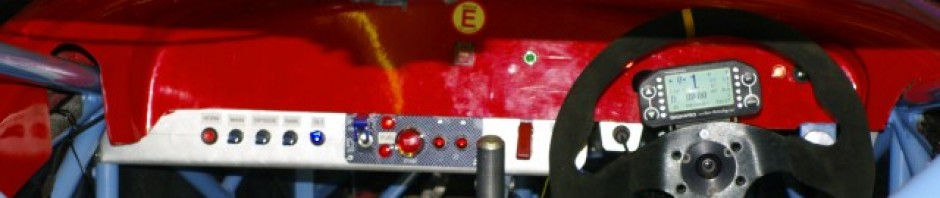
I’ve spent a fair amount of time calibrating the sensors…. and so far the channels that I’ve connected are correctly displaying the correct inputs. (the Oil temp sensor is currently disconnected hence the 136 reading) The Dash 4 gives me two lots of shiftlights, which are variable and individually setable for each increment, lap timing , predictive timing, on the fly calculated lap time delta in real time against my previous lap best. All very F1. It also give me 4 screens of data display, lap and sector times, min and max tracking and a host of over stuff. Every Pixel on teh display is configurable… so you can see it takes some time to position things correctly.
 I’ve elected to mount it on the steering wheel, which means that I also needed to fit the quick release connector just under the steering wheel, by making a small bracket, I also shortened the cable down to make the wiring nice and neat. Overall I’m pretty pleased with the layout but it has taken ages. This pic is through the spokes of the wheel, and the connector is set at the back edge of the dash chassis tube to help minimise intrusion of the connector plug.
Incidentally I had to calibrate the Kwaka coolant sensor by doing proper stove top experiments. Cooking it in a water bath of rising temperature, taking resistance readings at various steps using <cough sorry Mrs M> a Jam thermometer. Then plotting the graph in Excel and getting it to give me a best fit curve. Incidentally the equation is Temp =(-29.41*Ln(resistance))+209.41
I’m using the normal ETB oil combined oil pressure sensor and warning switch that I’ve previously used on my earlier Genesis, the equation for that was calculated previously by Tim in exactly the same way.
For oil temp I’ve opted for the slightly more expensive Race Technology unit, not least because the mounting thread matched the sump plug, and so fitting it is a dream, as I’ll just use it as the sump plug, where it will be fully immersed in the sump oil. Perfect.
 Now that brings me to the oil system. You may recall I had a problem in that the oil exits from the heat exchanger which feed the external cooler , clashed with the exhaust system. So I needed to relocate the exit, and plug the existing hole. Plugging the existing hole was easy, just wind in a 1/2BSP tapered plug with a good dollop of locktite and keep going until your temples throb, then peen the top of the threads to make it permanent.
Drilling and tapping the new exit was harder. Firstly I needed to drill a 19mm hole accurately and radial to the cylindrical surface. This was a job for the lathe. But configured essentially to run “backwards” in that I held the workpiece still in a vertical slide, and fitted the succession of drills in the chuck until I reached 19mm.
 Then I “tickled” the surface with an inch + 1/4 end mill to create a flat sealing seat for the dowty washer to seal the male to male 1/2 BSP to dash 10 JIC fitting. Then I removed the whole unit from the lathe and tapped it 1/2 BSP, which is a tap so big you have to turn it with a spanner. Incidentally that end mill falls into the Crocodile Dundee class of machine tools…. “That’s not a mill….. THAT’s an end mill”. ie it is essentially operated with utmost care from arms length and as far away as possible because it will suck you in and chew you up pretty quickly. With that the oil converter could be successfully mounted, and the outlets should miss the exhaust. you can just see the original exit above the right hand lower mounting bolt
 The Last thing on the oil system was to mount the sensor unit to the existing exit on the back of the block. This is tapped 1/4 BSP -28 TPI taper by Mr Kwaka… but the mounting is very small on the taper, and as such no fitting I could find would fit. So after discussion with Tony Gaunt… I decided to tap it out to NPTF 1/4 -27 taper… which is virtually identical. This allowed me to “open out” the taper in the block to accept a standard 1/4NPTF to -3 JIC hose fitting. The -3 JIC hose allowed me to locate the oil pressure sender away from the block and feed the pressure signals to the DL1 in yet another sensor cable loom. Needless to say I cleaned out the tapping swarf VERY carefully from the block.
Incidentally for the first time, I’m using the nylon braid type of loom binding , and I have to say I like it a lot.
 Back to the DL1…. I’m very impressed with this little “batwing” mount Duncan made. He really is fantastic at visualising this sort of stuff. It holds the DL1 safely and securely and also keeps it off the floor in a well protected almost water proof part of the car, while still allowing access to insert/remove the memory card. We wanted it off the floor, as we’ve been working very hard to try and make sure that the car can take passengers easily, with out all the normal stuff that tends to litter the passenger space. There are only the brake lines running on the passenger space central chassis tube.
To this end we’ve also mounted the extinguisher outside the main passenger space, in the area of the footwell that is beyond the diagonal reinforcing chassis bar at the end of the footwell. You can see it in the background of this picture. BTW the cable ties are all temporary fixing for the looms… the permananet fixings will be on on neat little mounting bases.
Talking of the floor, I’ve also run the full set of brake lines to the pedals , each corner of the car is now adorned with a coiled up loop of brake hose which is awaiting the hanging of the suspension and callipers…. which should now be very soon on the horizon as Andy is now soon to receive the new uprights and suspension from his custom machine shop. So the brakes are now just lacking the uprights, disks, pads and fluid…. all of which I have pending the arrival of the parts.
 The last piece of the wiring is the dash warning lights. With the shift lights and all the instrumentation on the steering wheel, and illuminated switches acting as self contained warning lights for main beam etc the only things left to mount are indicator tell tales, oil pressure warning , Neutral indicator and fire extinguisher button. These are now fitted to the dash, and I just need to wire up this sub loom. The lower dash edge needs trimming, but I can’t do that accurately until I get the rest of the bodywork, and I think I’ll make a little Ali or Carbon plate to cover up the hole from the previous owner’s paddle shift.
 The next thing to report is that I’ve made the seat, we did this in the usual cast foam method using two part expanding foam. This is a well documented but humorous process which essential entails you cooking your nadgers in the middle of an exothermic reaction with only a thin layer of plastic preventing you from being permanently stuck into the car. True to form we cocked up the first effort, but we now have a 80% formed seat, ready for trimming. Incidentally the orange plastic is a survival or bivvy bag. £2 quid from ebay we used several of these are they are the perfect option, being both large enough to form a seat in one go, and made of 500 grade plastic to help prevent “leakage”. The orange also goes perfectly with the blue powder coat, and calls to mind the old “Gulf Racing” colours from the seventies.
With the seat in place I could now finalise, and trim down the steering column. This I then TIGed together, painted and fitted to the car to complete the majority of this system.
So I think I’m almost at the limit of what I can achieve inside the tub. I need the body and floors to finalise the oil and water circuits, and finish the exhaust. The fuel tank is ready to fit, I’m just waiting on delivery of some insulation and a new pump to replace the “Known good working” one I bought from ebay which turned out to be “Known to be totally buggered”. grrrr
Then its time to hang the corners, the uprights, disks and brakes…. all of which I’m hoping to get from Andy soon, and which should with a bit of luck simply be a bolt together job.
Then there’s ARBs, + Dampers and pushrods, + pedals and body work fitting, so I have to admit I’m beginning to think I’m not going to make Anglesey.
 Talking of suspension that reminds me. I’ve mounted the bell cranks & bearing packs. These are made of 10 different components, including bearing races, ground and matched tubes + surfaces, shims and the billet bellcrank unit itself. Once they are all packed with grease and shimmed into place they spin like helicopters on the chassis mounts, with no detectable lateral play.

Like I said …. much to report. Next on my to-do list is finalise pedals, finish tidying cabling, fit fuel tank and mount diff. Then I’ve run out of stuff to do until I get the remaining billet and body from Andy…. which should hopefully arrive this week.