
Whenever I’m building a racer, I always try to work in complete systems wherever possible, because its easier to know that for example the brakes are done rather than, I’ve done this and I’ve done that but neither is finished.
However today we broke that rule. We got on with so much stuff that, and covered an awful lot of ground that it wasn’t possible to work in complete systems, not least because I haven’t yet got any of the suspension hubs or uprights.
First up …. brakes. The big pile of bits that arrived during the week were mainly all brakes and fuel bits, so I set too at the front of the car and started mounting up the brakes.
This required me to a make up the central ali plate, and the mounting angle bracket for the master cylinder reservoirs. The reservoirs are connected by -4 fittings and banjo bolts to the master cylinder inlets. I got these from Rally Design as a fairly reasonably prices pre assembled part. Clearly the feed lines are much too long, but for the price of a couple of 50p olives the fittings can be dis-assembled, the excess tube cut away and the joints remade. Unfortunately I don’t have any of the -4 olives, so this will have to be a job for next week. I wouldn’t normally use the braided hose to feed the master cylinders but in this case I was forced too. If you look at the feeds into the master cylinders you can see that they are extremely close to the chassis rail, so much so that only banjo fittings will work and these are generally only available for braided -3 or -4 hoses.

So on with the master cylinders, I needed to drill the floor mounts, and the pedals are bolted through from below. Here you can see them all mounted up with the new pedal in place too. The master cylinders are 0.625 inches and 0.70. I found this worked extremely well on the Genesis which used calipers of the same piston size, and Andy confirmed that this was what he also used.
I’ve mounted the master cylinders on the “outside” of the mounting frame, I would prefer to mount them inside the frame so that the mounting bolts are only holding them in place rather than transmitting the force, but to be honest I’ve compromised this to allow for ease of fitting and re fitting of the components.
Also in this picture you can see the banjo fittings, the front uses a double banjo, and the rear brake circuit is a single, it will split int a T piece below the diff carrier at the rear. The front master cylinder is also fitted with the brake light actuator pressure switch. What’s not obvious in this photo, is the same problem I had on the Genesis in t hat the master cylinder push rods are too short to have a reasonable length into the bias bar clevis, and have the pedal in the correct position. I don’t think wilwood make extension/ over long push rods… so I’ll have to make some extensions from hex bar.
While I was working away at the front of the car Duncan, was finishing the main firewall ,riveting it in place and sealing it. While he was at it he also sealed around the engine bay chassis members in attempt to prevent any oil spillage from seeping under the rails and ending up in the drivers space.
While Duncan was doing all the tin bashing, I got on with a couple of odds and sods like bolting up the steering column bearings, fitting the gearshift mount and fitting the main steering rack.
With the main firewall complete, it was time to refit the engine.
Part of the preparation for this was to fit the oil takeoff adapter that I had got from Tony Guant a fellow RGB racer, and acknowledged expert on the ZX10 engine installation.
 The adapter is to allow the oil to flow to the external cooler. The beautifully made, adapter plate, replaces the original Kwaka oil/water heat exchanger on the back of the engine, and also has the beneficial effect of simplifying the water circuit pipework.
Tony has had the adapter plate made up, as part of a batch for his own ZX10 powered Wolfe RGB racercar, and sold one on to me.
However we have a rather significant problem. In the photo above you can see the 1/2 Bsp thread in the upper outlet, and that the exhaust is extremely close, so close in fact that it is impossible to fit the oil fitting at all. It seems Tony’s exhaust layout is different to mine, and I’m going to have to do some hard thinking. The adapter can’t be rotated as it only fits to the engine block one way. My first thought is to plug this hole using a steel threaded and tapered BSP plug, and machine the face that’s away from the exhaust to take the oil fitting. But I do need to ruminate on it a bit more.
 Just before we permanently re-fit the engine we remember to reorient the sump reservoir so that the drain plug isn’t baulked by a chassis rail, and we also cut an access hole in the floor of the engine bay to facilitate draining the oil without removing the floor. With this completed we refitted the engine. This took a couple of hours, as the new powder coat has closed up some of the clearances, and every now and then we have to stop and back track in order to clear the powder coated threads of a few mounting holes. But eventually it’s all done up tight and the engine is properly nailed in again… Which is a major step forward.
Coo things are really moving on a-pace today. With the clock clicking around to 6 oclock, Duncan needs to get off, but I have just one more-thing that I want to complete today….. the majority of the fuel system.
 Andy has supplied a fuel tank, which is already fitted with a mounting plate for a CBR1000rr fuel pump.
I’ve checked the ZX10 and CBR workshop manuals and the pressure and flow rates of both pumps are comparable, or at least comparable enough to allow any differences to be mapped away using a Power Commander, so I see no reason not to use this tank. I acquired a fuel pump from Ebay, and fitted it up.
Also in this picture you can see the AN -6 fittings I usually use for the fuel injection hose. In this case I’ve used nylon braid covered hose rather than the heavier stainless steel braided version.
You can see that the hose is entirely in free space, with no possibility of chafe-ing. On the right is the fuel filter, which is mounted on some nylon cable tied fittings, and then the curved fitting that will flow up to the fuel rail. The pump outlet is 12mm banjo fitting on a M12 x 1.25 x 25mm long. I’m currently in two minds as to whether or not I should fit the MSA mandated fuel sampling valve… nobody else in club motorsport seems to bother, but I actually thing it could prove very useful for emptying the tank… which is an important consideration as the tank is in the engine bay, and you really don’t want to be sloshing fuel around too much.
With that, my feet and hands hurt quite a bit so I called it a day, but we’ve got a huge amount done and transformed the Sabre from a bare chassis to probably a 50% complete race car. More importantly with the engine in place I can now start sorting, wiring, oil and water circuits and the control inputs and logger outputs. Hmmm that’s quite a list perhaps its a 30% complete racecar.
Good progress.
I think I will have the opposite problem with the brake pedal, which worried me for a moment when I read your entry, but I remembered I had a free reign for the bulkhead which the MCs will mount to. Hope I got it right!
Hi Adrian
Is your brake balance remotely adjustable or a hands and tools down the foot well job? I bolted what looks like the same part to the Westfield and thought that it would be a case of adjusting with a screwdriver on the end of the balance bar. When I was spectating at Silverstone I noticed that most cars seemed to have remote adjustment for brake balance, are you planning to do likewise.
Cheers
Nick
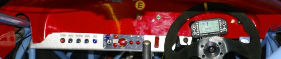
Hi Nick, yes its remotely adjustable by a knob on the dash, which twiddles the central bias bar remotely using a twisty cable. I just haven’t fitted it yet as I need to fit the side panels first. The way they work is that the pivot bearing in the middle is basically fixed on the rod. As you twiddle the rod it turns through the threaded bushes in the master cylinder clevises. This has the effect of moving the rod sideways through the clevises, which in turn moves the pivot point towards one MC or the other. As moving the pivot alters the ength of the lever ratio , it effectively alters the distribution of the braking force between the mc pushrods, and hence between the braking circuits.
Adrian
You’ll be fine… Tim is always cutting down his MC rod lengths to accomodate his adbnormal leg length… so you can adjust it eitherway if you need to.
A
Thanks Adrian, is the remote adjustment an off the shelf kit do you know? For various reasons I had the brake balance kit in and out a few times at the start of the build so know it fairly intimately… There’s a slot for a screwdriver at one end of the rod, I had assumed that this meant it would be a manual adjustment in the paddock to change the balance – not ideal for something that needs trial and error testing on the circuit. If there’s a kit that I can get that attaches to this to give remote brake balance that would be great.
Scrap that question, just answered it myself with a look at Rally Design’s website!
Cheers
Nick
You do need it cockpit adjustable, and you do fiddle with it pretty frequently… not normally 3 times a lap like the F1 guys do. But pretty often on a drying track, as things like the braking zones progressively dry out.