Apologies

Sorry for no posts for a while,  I have a whole stack of content to place on the site (including some old content relating to painting the car requested by the guys at Piston Heads)

But after a recent code update, I’m currently having difficulty getting WordPress to upload images successfully.   The infamous HTTP error while crunching.

The folks on the forums have been flailing around trying to find solutions for this for some time, resulting in a myriad of options to try.

So please bear with me the content will come I just need to fix this issue first.

Adrian

Posted in Winter 2009 Rebuild | Leave a comment

Fitting up the new floors

With both floors and side channels now made, it is time to fit them to the car.  So we postioned the car on the stands, and started fitting things together.

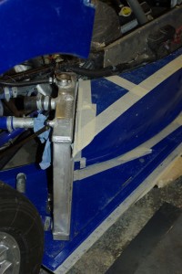
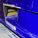
At the rear this involved reworking the radiator mounts, as the rads sit on the floor.  We made the decision to actually use the radiator to help stabilise the floor, via a couple of little Ali brackets.   We used this approach all last season  on the old Ali floors, and it seemed to work fine. You can also see in this picture that the radiator is sitting/butting up to the diagonal strengthening channel in the floor.  This is by design… we don’t just throw this thing together you know ;-)

Actually I’m thinking of reworking this radiator, so that it is a double pass unit,  it will mean moving the inputs and outputs around, but might make it more efficient.  I can TIG weld Aluminium and have a couple of mates with the right kit (my TIG is DC only), so it would seem foolish not to give it a go.

As part of the fitting  exercise I need to move the Fan to the inboard edge, so Duncan can fit a protective shroud to the outboard face and prevent damage from debris spun off by the tyre.

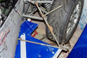
Up at the front the floor is fitted at the inboard edge with simple aluminium plates, that span across from the main chassis.

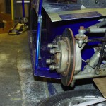
The outside edge is supported by a tension cable, which actually works extremely well ( I admit I was dubious)

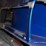
Once the sidepod is sat on the floor edge and Dzus fastened in place it all becomes pleasantly rigid.   The tension cable is shown next to the old steel support triangle that I previously used.  (although this one is actually from the back)

Once the floor is fully fitted (and I’m currently waiting for some longer rivets ), I’ll bond the curved channel down onto it with tiger seal.

Posted in Winter 2009 Rebuild | Tagged , , , | Leave a comment

Old Engine Strip

I’ve spent a few hours stripping all of the usuable parts out of my engine that went boom last year. As usual I’m both hugely surprised that these little engines stay together under the sort of loads we put on them, and be very impressed with the quality of the engineering.

Overall, apart from the casings, the oil pump, 1 piston, 1 rod and 1 crank the rest of the engine, and in particular bits that are known to break are all in good condition.

So I now have a full spare gearbox, a complete spare head, and a complete clutch + starter mechanism, plus a bunch of sensors etc.  It was a very useful exercise as I’d never stripped one of these engines before..

Anyway here’s a couple of shots of the carnage, plainly no 3 bearing got a bit warm.

I won’t bin the casings, but reassemble them empty as they will come in handy for my next project.  More of which later.

Also as is traditional in CAM7 circles, the crankshaft must be exhibited at one of our regular get togethers for the general amusement of all.

Posted in Winter 2009 Rebuild | Tagged , , | Leave a comment

Progress Continues

Well progress on mouldings for the new side pods continues.   Since my last post we’ve laid up the complete right hand floor , buck, mould and moulding.

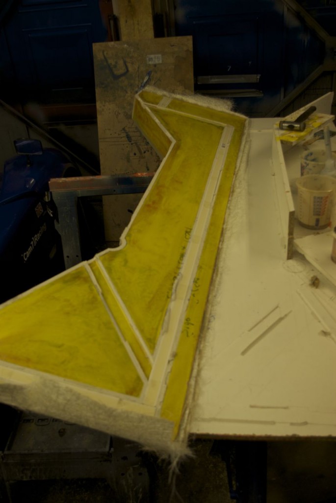
So the usual process applied, which was.  Make the buck out of a sheet of contiboard, with appropriate joints and upstands.  The buck you’ll recall is an exact copy of the part.

Where there were joints in the wood, you either cover these with a small bead of pasticene smoothed into a concave quatrant using a ball type tool, or if they are convex corners you cover them with clear cellotape.  Then you wax the whole surface a couple of times (taking care not to leave cloth marks in the plasticene), and apply a  very thin coat or release agent, and let that dry.
IMGP1504_2

Then lay up, 2 layers of gel coat, Layer two goes on when layer one is still tacky, and soft enough for you to lightly touch it and leave a fingerprint, but when you remove your finger you have no gel coat on it.  That then goes tacky, then you lay down some CSM tissue, and let that go tacky,  and finally enough layers of CSM to make it properly rigid.  I also added a layer of 3mm coremat. which appears to be a foam with pre stamped channels across its section.  These fill with resin (hence the coremat’s monumental consumption of resin) which form a sort of honeycomb matrix. You then leave it to go off for a week

And eventually you end up with a mould.  Here’s a shot of the buck with the mould released,  you can see that the plasticene has pulled away from the buck and stuck to the mould.

The mould has yellow gel as the first layer and orange gel as the second.

Then you trim the edges, I’ve a little air powered die grinder that I use for this fitted with some little 3/4 inch diamond cutting disks.   It fairly zips through the trimming of this 8mm thick mould without chipping.

Using hot water you wash off the release agent and plasticene and examine your creation.  Argh to our horror we discovered that the surface of the mould was showing the classic orange peel effect of swollen wood grain. We had re used a sheet of contiboard that I had bought way back in November, and it seems the chipboard substructure had absorbed moisture in the garage, and swollen, marking the smooth plastic surface.  It wasn’t obvious on the buck,   but certainly was hugely obvious on the shinier surface of the mould.

Gah!.  So break out the sanding pads, 600, 800, 1200 grit wet and dry, rubbing compound and polish. And after about 4 hours you end up with a bright yellow mirror!.

So with the mould now properly smooth, another four hours of waxing ensued, followed by a light application of release release agent. So now having made the tool.   I can make the part.

The actual moulding is very thin, 1 layer of gel, 1 layer of tissue, 1 layer of CSM,  coremat in the reinforcing channels, topped with a strip of CSM. And then a layer of woven rovings over the whole lot.

I was standing outside working in a bit of spring sunshine applying the last layer of wax before the moulding began,  Duncan wandered over and was promptly dazzled by the reflected sun on the moulds glossy surface.    ”Bl**Dy hell that’s shiny, I think you’ve got the hand of this now” said.

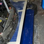
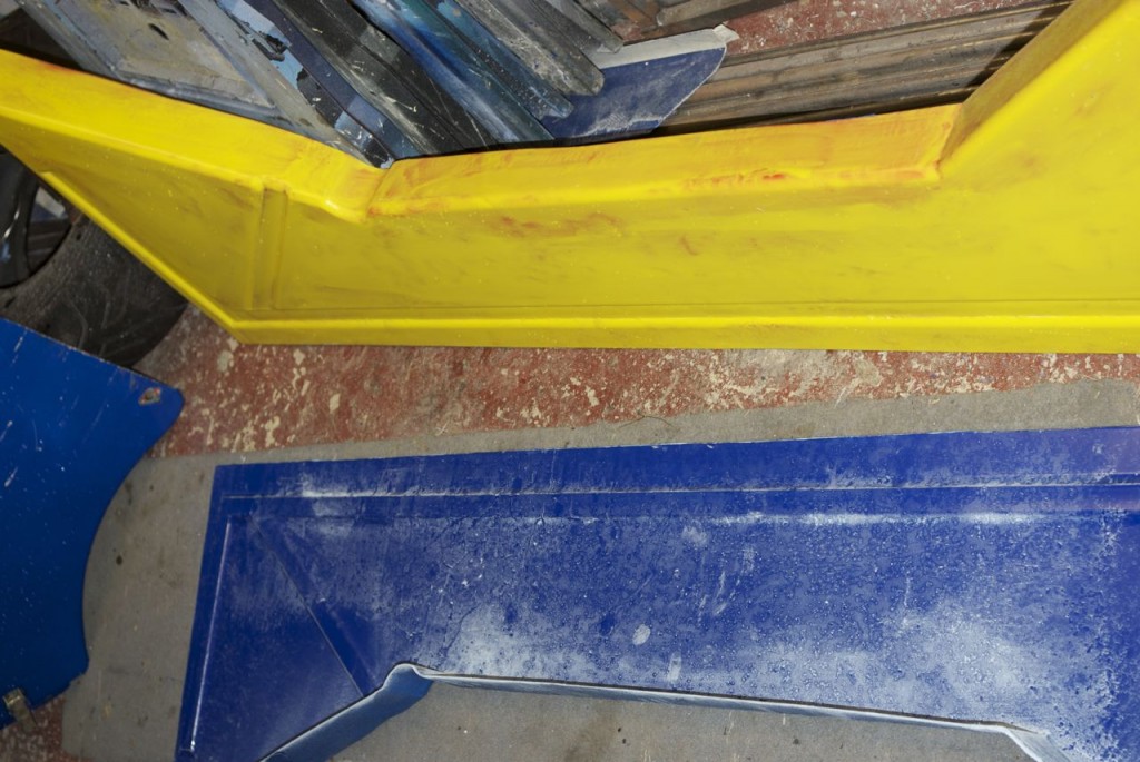
Below the trimmed and polished mould is yellow (it is also covered in raindrops) , and the new floor, still dusty from being trimmed is blue.
IMGP1560_2

So, as this has plainly been a very large amount of work (we started in November, but usually only work saturdays) was it worth it to make 4 parts?  Bearing in mind that I could probably made both floors in a weekend and the more complex curves of the interior channels, would have taken probably another couple of weekends.  Hard to say,  It certainly hasn’t been an expensive exercise as the materials are cheap, and I’ve pulled a few more kilos out of the car, but it is very  time consuming.  The pay back is that I can now make a new floor in a a couple of hours, and will have the ability to actually set the ride height legally  now .   Also I’ve learned a lot (which for me is always a valuable objective in itself) , and I’d now be confident about building larger components with a high quality face surface…. like exterior bodywork. :-)

Plus I find it a really really interesting process as sticky, nasty smelly polyester resin goop, metamorphoses into a nice smooth part,  If only I had some decent design skills I could almost say a thing of beauty.

Posted in Winter 2009 Rebuild | Tagged , , | Leave a comment

More Side Pod Progress

Sorry for no recent updates,  but actually that’s been because I’ve got nothing done since the last update in mid December,  we’ve been away on holiday over Christmas you see and now I can say I’ve learned to snowboard :-)   But today I got back in the garage groove and started assembly of the new side pod channels.

Basically this involved lots of measuring, cutting and sawing of my nice new mouldings.  We discovered that I’d allowed quite a bit of extra material in a couple of dimensions and so one of the things I had to do was cut off the return on the duct moulding.  That done, we could set about getting everything aligned.

We also had to cut both the bottom return of the existing sidepod, and cut out the existing duct sections.  It’s all roughly to shape and now needs final fit and finish.

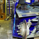
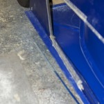
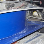
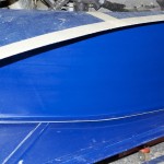
Hopefully You can see in the sequence of pictures below, what I’ve been trying to achieve for all these weeks.  Namely a complete smooth channel from the front wheel arch, (where it will be fed from both the frontal openings and an upswept front floor)   all the way along the side of the car, without ever reaching the outside surface, The duct exits  through to the radiator. Along its length  I’ve been trying to keep the surface transitions smooth and gentle so the airflow stays attached.

A secondary objective was to straighten the edge of the existing pods, and fit an horizontal floor edge to help stop me getting a ride height DSQ (The old side pods had uneven lower edged, which wrapped round under the car, and which made it difficult to ensure the car was at the legal 75mm height).  This new horizontal floor edge may also help the underbody create more aero, by stopping air bleeding in underneath the car and disrupting the low pressure area there.

Overall I’m pretty pleasedwith the result, but the channel hasn’t ended up as deep at I would have hoped. Still it has got to be better than before.   If you look at the sidepod as the Radical PR6 you can see it has a similar arrangement, but the entry lip of the rear most body work is much further forward.  I suspect this is to stop the air escaping as it passes the top of the duct transition.   We may well think about doing something similar.

Posted in Winter 2008 Rebuild | Tagged , , | Leave a comment

And finally, we get to make a moulding.

IMGP1374

Most of this weekend seems to have been spent apply mould release wax to the side pod channel mould, and then buffing it off again.  On new moulds, particularly large ones, its is good practice to apply a fair few coats before the mould’s first use.  Some sources say as many as 12, but I guess that is for production use.  So I made do with four, and even then my shoulders hurt afterwards. Actually before I applied the wax, I decided that having a textured surface on the moulding really wasn’t good enough, so I set about it with some 120 grit paper, then 380, then 600, then 1000 grit and 3 hours later I’d got the surface finish to be much, much better.

After that I fastened it down onto a contiboard based board, and made plasticine fillet at the bottom joint margin. Then it was on with  the release agent, and a coat of blue gelcoat (500cc). This picture is actually the back of the mould, and the small strip of gelcoat will make the return where the side pod channel will fix to the floor.  The other side of the mould is fully gelled up as this is for the right hand side channel.  When I do the left hand side one, I’ll fully gelcoat this side, and have a short return on the other.

So there then followed a layer of glass tissue, 1 layer of CSM, and 1 layer of Woven Rovings.IMGP1373 and once again I’m smelling of styrene.  But as I’m now working on the outside of a male mould at least this is now pretty straight forward to layup, and consolidate with a roller.  Although the compound curve of the top surface, makes wrapping CSM, and woven glass round the edge  a bit challenging. To help you orientate the part, the horizontal return laid up on the face of the contibard will form a mating surface with the vertical side of the upper side pod. and the big ski jump at the right hand side will actually form the channel behind the front wheels

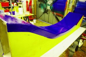
So after about 3 hours, while the glass was still a bit green and flexible, I released the part from the mould, and voila, see below for the results.  I briefly plonked it on top of the mould so you could see the finished part…. although it is actually upside down.    As it was still green I then placed it back on the mould so that it adopts the correct shape as it properly hardens off

A quick tip, that I learned tonight,… if your doing a partial layup on a mould surface you tend to get lots of drips and runs on the area where you’re not producing the moulding,  I was concerned that this may be hard or a least terribly tedious to remove ,as without and fibre reinforcement I might have to chip each drip and run off individually, possibly damaging the mould in the process. So with my last batch of resin,   I made  a little extra and painted it on the unused part of the mould.  Into this I patted all my small offcuts of CSM and rovings and left them to go “green”.  Once it had greened off I just pulled the single layer loose sheet, and it came off a treat, cleaning up all the overspill from the mould in the process.  Lovely :-)

IMGP1375

Any way enough of that… this is what your waiting to see. As I said it is upside down,  But you can get the idea if you imagine the front wheels are at the left of the picture.  The white line, by the way is the residue of the plasticine fillet between the base board and the mould, that will clean off with hot water to reveal a nice smooth radius. And below you can see the mould has released cleanly, plus my camera really likes yellow!

The sharp eyed among you will spot that the extreme left hand edge of the “floor” part is curving under its own weight.  This is mostly because the part is still green,   but I may need to add some additional stiffeners to this bit. Tomorrow, I’ll trim both this and the floor and put them together so that you can see if my plan has come together.

IMGP1376

Posted in Build or Repair, Winter 2009 Rebuild | Tagged , , | Leave a comment

Talking of Little Rubs

In my previous post, I mentioned getting “rubbed”  by another car in the middle of the RGB pack.

Well here’s a shot of our last RGB race at Mallory park,  after a poor qualifying I’m at the back and you can see I get slightly bumped by Andy (I think) just before he gets spat out of the pack in front of the bright orange car.

Its not always like that… in fact rarely. Poor chap it was his first ever race too.  Not his Fault,  not anybody’s as a matter of fact , RGB is now so competative that all the gaps are closing quuckly and he had nowhere to go, bit of a baptism of fire though, and fair play to him for collecting it before the barriers.

Posted in Mallory Park, Racing | Tagged | Leave a comment

Yeah Baby!

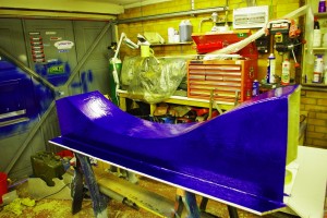
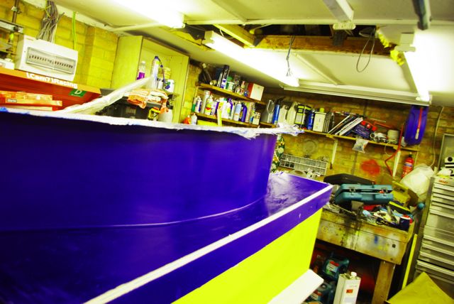
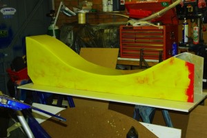
IMGP1372Now I thought I was making an air duct for the side of a race car, but it appears that instead, I’ve been making some wierd piece of plastic sixties furnatrue.  A bright yellow Chaise for Chrstine Keeeler perhaps? 

Well you can tell from this photo that I finally managed to complete the mould for the side pod tunnels.  It took  fully, five  layers of CSM, 3mm of coremat, about 10 litres of resin  and a number of extra layers at the edges but we got there eventually.

Remeber this is a mould, so it is the negative of the part required, and will actually produce a hollow duct with a curved inner wall.

In this picture the front of the car is towards the left, and the white panel below will be the outboard vertical face of the side pod. The yellow face, facing you will be the top of the tunnel, and the radiator will be placed diagonally across the end with the extra red gel goat.

It wasn’t all plain sailing. As I feared, the PVA release agent had raised the wood fibre texture on the hardboard which makes the curved section, and this was unwilling to release from the mould.  The hardboard had a better grip on PVA/Mould than the adhesive that held all the hardboard layers had.  As a result,  while it would release from the mould in small sections the hardboard would then break up or delaminate. So we ended up having to scrape it off in layers after wetting it out with water.  Imagine  removing the heaviest, most overpainted wood chip wallpaper without the use of a metal scraper and you’re somewhere close.  It took about three hours, using sharpened softwood mixing sticks.  Also  it left the mould with and interesting texture akin to that of Feaux Leather.   I rubbed that  back with 360, then 600 and 1000 grip wet and dry. Its not perfect… but hey its a race car!.

The other thing we did today was epoxy a 100mm strip of Kevlar down the  underside of the floor moulding we made previously.  Kevlar, especially when bonded in with epoxy, is ridgid and makes the moulding very hardwearing.  This will be very important as the side pods will need to stand up to the odd glancing “rub” when in the middle of the RGB pack.

Posted in Winter 2009 Rebuild | Tagged , , | Leave a comment