Stop and Turn

I’m currently running two projects so today was mostly spent, clearing the engine bay of the 1275GT Mini, to try and get it ready for repair and painting.  the main issue being that someone in the past has spilt brake fluid around the master cylinders, this has lifted the paint and corroded the bulkhead…. not terminal… but not the sort of thing you want to leave un treated… so after stripping out the cabling, master cylinders wiring (although it did take 2 hours lying on my back in the footwell struggling to get the split pins out of the Master cylinder Clevises) and all the ancillaries I attacked it with a rotary brass brush.   Still you’d rather hear bout the Sabre I suspect.


On Friday night when I was Andy’s I picked up some Aluminium blanks for the front and rear bell cranks, and the dimensions of the push rods.  So I spent 45 minutes knocking up a spacer for the   bell crank hub as I don”t currently have the bearings, and then mounted up the bell cranks, I also tacked up a pushrod  to 560mm in length, and fitted some of my now vast collection of rose joints.  All of this meant that I could fully assemble the front right lower suspension.  The ali blanks are what were formerly used  in the production car, but they didn’t stand up to the load, so I’m currently waiting for some later cut steel ones.  Having said that the geometry is right, and it allowed me to model the front suspension Kinematics.

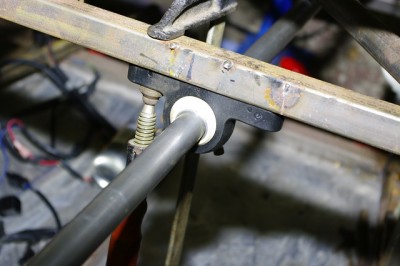
The  point of all this is to finally locate the steering column, specifically to allow a double  offset UJ to be installed. 

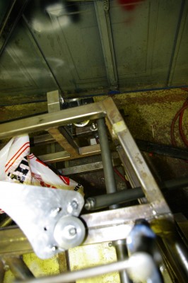
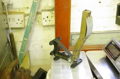
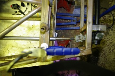
The good news is  I think I’ve found a solution.   If I shift the column about 1″ to right I can offset the column, and now with a working front suspension I can check that with it in this position that the pushrod never clashes with it.

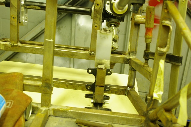
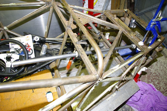
You can see here that the column is now nicely offset and a short second link can now be fitted between it and the rack to remove the spear effect I talk about in a previous post.

Moving the bellcrank through about 6″ of travel I can see that the column nevers gets within 10mm of the pushrod, and then only in absolutely full droop, which is only ever achieved when the car is on the jacks, so with the car on the ground and the suspension loaded up we should be fine.  Excellent, I can now get on with welding in the bosses to take the steering bearings… and with the wheel fixed in space, the  gear shift, pedals and all the bits of the hands, arse, knees, feet and eyes relationships that contribute to driver comfort can start to be finalised.

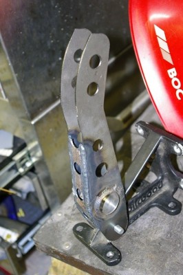
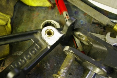
Talking of pedals I’ve started welding up the brake pedal blanks.   Tigging in the tube was a bit hard, and unsuprisingly the tube has distorted slightly so that the bearing tightens a bit as it runs through so I will need to ream it back to size on the lathe.   Here’s a pic its currently about 60% done.


Posted in AB Performance Sabre, Brakes, Steering | 2 Comments

Autosport Bargains

Tim, and I took a well earned day off work and headed off to the AutoSport show for one of the trade days.  As we have a competition licence we geto go before the crowds arrive.  Well I say the Autosport show…. it felt more like a RGB paddock reunion as we spent most of the first two hours shaking hands with our mates and chatted around the 750 Motor club stand.  It was in fact a an RGB get together with the added bonus of a race car engineering show being put on near by :-) . And as always we both came away fired with enthusiasm.   I suspect Tim is refitting his engine even as I speak…

Part of that show was the Sabre, which Andy was exhibiting on the club stand.   I happen to know Andy had been working to flat out after his long overdue Christmas break to get it ready and it did indeed look absolutely great.  It was Derek Jones’ car and looked great in its new Black and Orange livery…. I’d show you a picture but lack of card in the camera I was lugging about was a bit of a hindrance.

:-(  

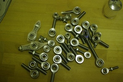
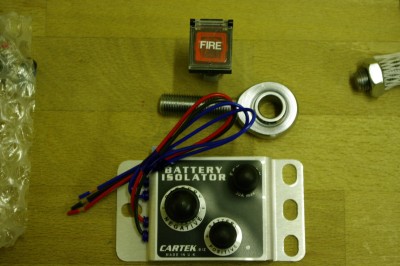
However, I did come back with some show bargains for the Sabre,  firstly there is  this huge pile of engineered bling, which represents a not inconsiderable chunk of cash and is some 80% of all the suspension joints on the Sabre most of the outboard joints are spherical bearings rather than7/16  rod ends.  No nasty poly bushes on this beastie.  There’s even a couple of joints in there for the gear linkage. These came from those nice blokes at McGillsMotorsport.co.uk who were running some good show offers, and who apparently took 9 tonnes of gear to the show, so I thought I’d relieve them of a couple of Kgs of it.  I also got a rather bling master switch panel…. which was very nicely made on Carbon fibre and cost less than i could have bought the switches alone for, plus I didn’t need to expend any effort to make it… whats not to like?

I’m not entirely sure where I’m going to mount the salt cellar though.


Other spendy treats included a Cartek electronic isolator, again a show offer at a very good price.  I ummed and Aahs over this for a while as generally I agree with Tim on the keep it simple stupid principle, but the clincher was a returning customer, who had had 5 years happy service from his and was now buying another one as he had changed his car and wanted the same system again.  Also it is totally titchy, and much lighter than I expected, that’s’ a 7\16th rod end for comparison.

Also shown is a very light new lifeline extinguisher trigger button…. not as it happens a missile launcher button.


Lastly I’ve just been over to Andy’s and collected my Quaife QDF7ZR Auto Torque Biasing Differential.  now that I have this I can get the engine aligned and the mounts made.  While I was there I was also collected the ZX10s airbox, and the bits I needed to build up the front right corner, so I can check the kinematics and finally place the steering column.    So Lots of bits to get bolted on :-)

Posted in AB Performance Sabre | Leave a comment

Knife Throwing Anyone?

Do you like my new collection of totally authentic Tuareg throwing knives?  The ones on the left are for filleting your enemy’s gizzard. I plan to start a knife throwing act and I’m just waiting for the big rotating wheel and the squaw outfit to turn up for my willing assistant.  (but that’s another story).

Still silliness aside this is the collection of laser cut pedal blanks that turned up today.   There are enough here for two complete pedal sets.

The brake pedals have the large complete hole in the middle that exactly matches the balance bar tube supplied by Rally Design.

The throttle have the semicircular cutout to clear the balance bar control cable… and the clutch has the large number of holes near the base to (hopefully) allow the clutch ratio to be tuned via a small bell crank.

Not bad for 38 quid, and one of those things that I have no hope of making remotely competantly by hand.  These really are rather nice. From brain to reality via Lasercut of Peterborough.

Here’s a mockup of the brake pedal…. I cant mock up the others, as to be honest I haven’t yet worked out how to mount/pivot them in the footwell.  I’m going to try and mount them on a frame also bolted to the Wilwood unit.

Here’s a mockup using the newly arrived blanks, I’ll weld up the pedals themselves this weekend, once I’ve dug the big bottle of Argon out from the other side of the garage.


Posted in AB Performance Sabre, Brakes | 2 Comments

Sparky Goodness

Is it a bloke thing… learning how to weld?  Actually its clearly not as those good folks over at The Bluebird project proove, as one of their key volunteers is someone called simply “Girl” who apparently is the best Ali welder on the team.  Please support them if you can, their efforts to resurrect Donald Campbell’s hydroplane after 30 years in the mud at the bottom of a lake makes my quest simply to go fast , round and round in circles seem somewhat feeble.

However on with my project in hand, and this is rather a big update I’m afraid.   Well since Christmas I’ve mainly been devoting time to to completing the steelwork on the chassis with a view to getting it powder coated before the end of January (though that plan may change).  To this end my two tools of choice at the moment are Mr Sparky the angle grinder, and Mr Zappy the Mig Welder.

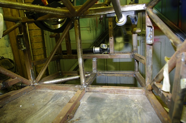
So far I’ve completed the front foot box, which involved building a whole new floor section, perimeter frame, diagonal bracing and vertical braces.   I’ve also cut out the compromised front bulkhead members and replaced with appropriate round section tube and again a diagonal brace .    These few words represented some 10 hours of solid work, and the result can be seen below. Everything below the midline in the footwell is new, as is the diagonal brace and round tube in the foreground.
After a day of vibration from welding, cutting, & grinding my carpel tunnels flared up big style to the extent that I spent many hours fighting the dull ache in my wrists and the loss of sensation in my finger tips.   To that end taking a rest from the heavy gauge stuff seemed a good idea, so I invested a day over the new year cutting the ZX10 loom into shape.  This just simply takes hours, but the only way to do it is to pore over the zx10 circuit diagram, and systematically cut out all the circuits and components you don’t need from the bike loom.   The objective is to leave yourself with a dedicated engine management loom, with just a few connections to made to provide power and control via the main car loom. everybody in RGB seems to do this in different ways, but my objectives are.

1) Cut out all the lighting circuits, as these will be controlled by the car.

2) Defeat all the safety interlocks by removing the various diodes and switches in the circuit and identifying which ECU Pins need to be earthed to permanently fool it into to thinking it is safe to start the engine.

3) Remove all the bike switchgear, and transfer only the necessary functions to allow the engine to run properly.

4) Identify the switched and unswitched supply to the ECU, the fuel pump and fan circuits, engine start,  engine kill  and expose all these  as inputs from the main car switch gear and or route to the kill switch appropriately.

5) Remove all non essential ancillary components.  Including vehicle down sensor, key switches, fuseboxes, relay boxes etc etc.  where necessary defeat or mimic the replaced component if the ECU will throw an error code without it.

6)  Identify which circuits and control lines should be sent to the DL1 for logging.   Obvious ones are throttle pos, tacho feed, water temp sensor, gear position, airbox pressure, neutral indication and so on.

7) I also retain the clocks signal wires, as the zx10 only displays its fault codes on the clocks as full error codes.  Gone are the nice helpful LED flashes that the Honda used instead the ZX10 only issues codes via the clocks… so I’m going to need to get a duff set of clocks of ebay I think.

Tracing every wire in the loom in this way, also helps you check if there are any wires damaged, abraded or generally butchered by the former owners attempt to fit an immobiliser/power commander or other aftermarket device, I’ve got a few of these, particularly around the stick coils so I think the previous owner fitted some sort of performance enhancement gizmo.

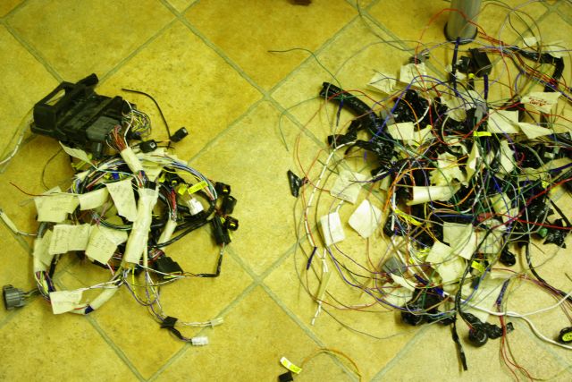
After a day at the Kitchen table, tracing wires I ended up with the following piles. On the left is the now minimalist Engine management loom ready for binding, and all nicely labelled up…   right is all the stuff I cut out.   I’ll post a schematic of this once I can get my paper copy scanned.
 I’ve had a few bits of bling arrive.   First on the list is a new Dash4Pro and Dl1 mk 3….. which I will use as my primary instruments.  Then came a new steering wheel, brake balance bar and brake adjuster from Rally Design.    These will get welded into the the pedals outlined in my previous post.  Which also incidentally are now with Lasetcut.ltd.uk in Peterborough, who will laser cut me enough for two complete pedal sets (in case I cock one up) for the princely sum of 30 quid.

The steering wheel from Rally Design, will be augmented by a very nice quick release boss from Go-racing.co.uk. And lastly some CDS tube from Merlin for welding in the roll hoop diagonals.

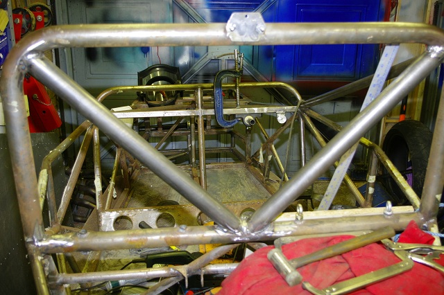
 Talking of which… last weekend the new diagonals got cut, welded and fettled in, the added bonus is that  they also form an effective headrest, so I don’t need any additional steel for that.

The little bracket on top is for the rainlight that I’ve ordered from www.competitionsupplies.com, and which Chris and I made together last night. and in front of this, is the little welded on tray that holds the DL1 GPS sensor.  In this picture you can also see the fitted brake bias control wheel on the dash frame to the right of the steering column.  I hope you can also see that the chassis is looking cleaner  at the front as I’ve now decided to do pretty much a full build before I get it powder coated and the light surface rust is just annoying me…. so I’ve started wire brushing it off.
 The Steering column remains an issue, as I can’t work out its location until I get the push rods fitted.  Andy has enough components waiting for me to collect so that I can build  up the front right corner…. that will give me the push rod kinematics and from there I’ll know where I can put the steering column. Andy also has a new diff for me which is necessary to arrange engine mounts…. so we are cracking on.

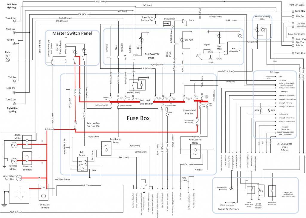
The main wiring diagram is now largely finished too, after a many hours thrashing Visio into submission.  Current plan is to use an MTA modular fusebox, with a separate fuse for every circuit, so that the transponder is not killed by a sidelight failure. I’ll be ordering the components and cables for this this week.
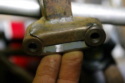
The last thing to report tonight is that Chris and I made this little bit of steel tonight.  It doesn’t look much but is actually vitally important.
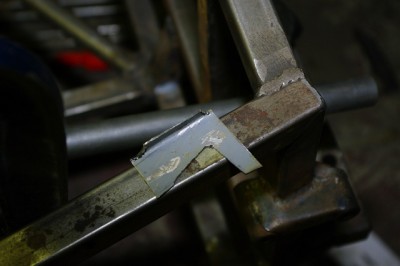
 

It is in fact the lower half of the support bracket for one of the front suspension mounts.  These were incomplete, as the chassis was never finished.   As usual I should say that if you buy one from Andy it will all be complete and beautiful,  I’m just finishing off one of the prototypes chassis.

So that’s a big update… but I think I’m up to date now. 


Posted in AB Performance Sabre, Lasercut, rain light | 3 Comments

Virtual pedals

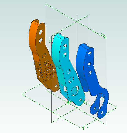
Well its Christmas day, so Garage time is most definitely not happening today.  So in the evening quiet time when we’re all sleeping off the day I knocked up these in Alibre design.   Its amazing what you can do with half an eye on Downton Abbey, a tummy full of mince pies and dram of Lagavulin close at hand.

Posted in AB Performance Sabre, Brakes | Leave a comment

On with the Footbox and Pedals

 I can’t really do very much more at this stage on the steering, as a) I’m waiting for a steering wheel boss and b) I need to ask Andy a question, and he’s gone on a much deserved holiday to Canada with Shona.

So today I cracked on with fabricating the pedals and the foot well.  As always I should say that I’m only doing this work, as this is the first development chassis and I knew it was incomplete when Andy and I did the deal.   If you buy a spanking new Sabre yours will come all new and resplendent in powder coated loveliness.

One of the things I need to fabricate is a pedal box.   I could just go out and buy something like an OBP box,  but to be honest I felt I could make something more rigid, plus I’m a cost conscious cheap skate.

Andy fabricates his pedals out of some 1/2 x 2 inch box section, but I’ve always had a hankering for a set of Tilton pedals, not least because they have  a neat little milti segment throttle linkage, which allows the rate of throttle application to be varied through the pedal stroke.  Both Tim and I have come to the conclusion  that mid range throttle granularity is highly desirable…. particularly when racing in the wet, when its really easy to spin up the wheels.

This particular design is also a downward pull type which might help my cable routing too.


So I made a start on the brake pedal assembly.  I have a set of old Willwood pedals + balance bar which were fitted to the Genesis,but to be honest I hated them.   The pedal pads were all at the wrong angle for my driving position, in fact I think they were designed for a non race car with a normal saloon style seating position.  They had been getting stiff before I changed them anyway… so they had languished in the spares box ever since. However what they do have is a very rigid  and very light base casting.    Unfortunately the steel pivot tube had corroded in the casting so had damaged the bore, so first order of the day was to nock up a little brass bush on the lathe with an 8mm bore. You can see it here in the centre of the Willwood casting, alongside the correded pivot and the pedal I’ll be discarding.

Then I set about mocking up a pedal, this is simply to try and get the proportions and angles correct.   My arse is only about 2″ off the floor in the car so the pedals need to be very similar to a formula ford in profile.  After a bit of random cutting and welding I’d mocked up a suitable profile, and testing it in the kitchen by sitting on the floor wearing my race boots, indicated that ot would be fine.  I’m sure you’ll agree it looks exactly like the Tilton pedals :-)  .  Actually the plan is to transpose the measurements to a cad drawing and get the pedals laser cut from 2mm steel. I don’t like the idea of welds across the load bearing side surface of my brake pedal.  I’ll use the same profile for the clutch pedal, although in 1.6mm steel, and then do something different for the throttle.

With progress on the pedals well underway, I really need something to mount them in.   The chassis has the floor of the pedal box missing.  Actually I think Andy went through a design change after this chassis was built, and this chassis’ front floor features a high pedal section.  So I then spent the rest of the afternoon, making a jig for the new floor, and then welding it in place.  in this picture everything below the mid rail is new.  You can also see the stubs of the transverse bar that I cut out.   The whole thing of course needs triangulating and I don’t intend to mount the new pedals on a chipboard shelf, but you get the idea. Luckily the transverse floor bar falls nicely to act as heel bar to brace my feet against. Incidentally the vertical brace is now compromised, so I intend to cut that out too and properly triangulate the aperture in the passenger footwell.

#


Posted in AB Performance Sabre, Brakes | Leave a comment

Steering Coming Together

After a couple of days wrestling a 1275cc A series engine out of the mini (output a whole 80 odd bhp)  today I managed to get a bit of work done on the Sabre.

firstly Chris and I dropped the chassis on the scales…. it came it at 89.7Kg  which is indeed a bit lardy…. I hope Andy’s new bodywork is amazingly light or I could still be way above the weight limit.  The engine weighs 63Kg.

After that I thought I’d start on the steering.  The Sabre has nicely machined mounts for a standard Escort rack, which is fitted with either a 2.2 or 2.4 fast rack.   The only modification Andy makes is to machine the standard square mount down to a cylindrical cross section.  So the rack mounted very easily with just four bolts. 

Then it was onto the column itself.    This is 16 gauge CDS steel tube 22mm OD.   I don’t believe in reinventing the wheel and Tim has previously used some nice lightweight, self lubricating, engineered plastic bearings for his mounts in the J15.  These seem to work well, so I blagged a couple off him and a length of CDS that he had floating around his garage, and mocked up the steering column.

Sabre Steering Column
The column is the only bit of steel that isn’t slightly rusty.  Like Tim I had to make up some little aluminium collars to mount the tube in the bearings… but that’s what lathes are for.  And Chris and I had a some good fun doing it.  Infact the slightly better fitting one his his work not mine :-)
 
 Andy’s factory complete chassis use a nice Aluminium tube and nylon bearing to act as the front mount for the column, and also support the AB Performance paddle shift.  But as cant use a paddle shift due to RSI in my wrists… I don’t need it and I’ll need to engineer a lever  to change gear too.
 
 
While mocking up the column I did have one concern. Andy has worked hard to keep the steering column on a straight  run from the rack input shaft.  Unfortuately this also means that when the rack arrives first to the scene of a frontal accident it also directs some of the force up the column towards me.  In other cars you either correct this with an offset column and 2 UJs or a collasible link in the column.   I need to cogitate on this a bit, as there’s not really enough space for an offset column, and I don’t want a nastly collapsible link in the top.   One alternative is to fit a circular safety collar on the top of the shaft… but this sort of defeats the purpose of using nice light bearings.  Or I might just ignore it.
 
I also need to replace that chunky CV joint.


Posted in AB Performance Sabre, Steering | Leave a comment

Making a start.

Tonight after refitting the rear subframe on my Wife’s mini I thought I’d move the engine for the Sabre into the engine bay.

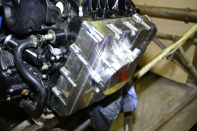
This necessitated fitting the billet sump Andy had supplied with the big box of bling I collected earlier.  After the usual fitting of modified pickup and baffle plate I had the sump fitted.  Interestingly the is one of Andy’s third generation sumps and consists of a second bit that is bolted to the main sump pan to act as the oil reservoir.  This means that you can position the oil drain plug in any orientation.  Also I added a tab washer to the mounting bolt near the plug so that I can lockwire it in place.

Of course the main reason for this is to give the engine a flatish sump to sit it on the floor in the engine bay.

2008 ZX10 Billet Sump


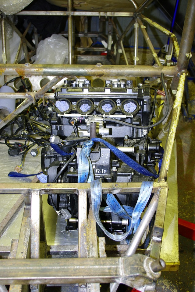
So out came my trusty engine crane and after a bit of jiggling and removing of ancillary components, I manged to get it to sit reasonably in the engine bay.  One of the design features of the Sabre, is that it has equal length driveshafts and consequently a center mounted diff.  Of course this means that the whole engine is offset to the drivers side as the output sprocket is on the left of the engine.  I remains to be seen what this does to the corner weights and handling.

Anyway here’s a pic of the engine loosely in place.

With the main cockpit now empty of engine, I of course, climbed in and made “brumming” noises.  The cockpit space really is huge, I may even need a booster cushion.

I then spent a few minutes identifying the various sensors, on the lump and removing any aftermarket rubbish.  This engine has plainly been owned by someone who wanted to get his bike to perform, as I think its been fitted with a non standard big bore exhaust,  the sump pan has been ground down to accommodate it, and some of the stick coil leads have aftermarket pick ups on them to drive some form of power commander.  I’m going to need to go through this loom very carefully.


Posted in AB Performance Sabre, engine fitting | Leave a comment