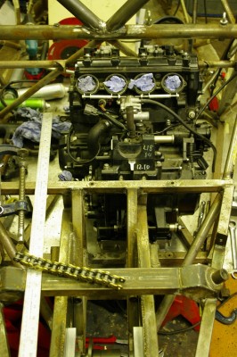
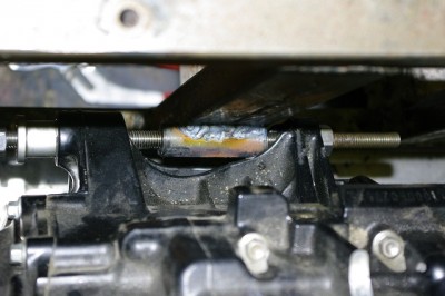
This is going to be exhausting.

Did you see what I did there?   Yes, the terrible pun signals it is time to start on the exhaust for the Sabre.   Andy needs to order in the Mandrel bends for me, and currently I frankly have no idea what I need.

So I thought I’d better start planning the general shape of the primaries.

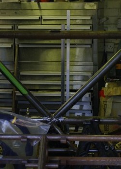
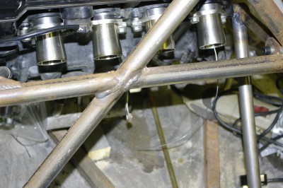
My first idea was to do it on the car.  So I mounted up the exhaust headers and began faffing around, but planning something in 3 dimensions is a virtual impossibility, particularly when you’re just modelling something that you don’t actually have in your hands yet.

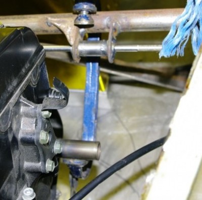
Inside no 1 outlet on the far right is a small disk of aluminium with a 1.6mm home up the middle the idea was to centralise the aluminium welding rod I had cut to the right length for the primary (you can see it hanging out of the port).   The idea was then to bend this to shape using  100mm bends (basically around a tin of filler).  But I quickly lost the will to live trying to do it this way… what with the access problems due to all the chassis members around the back of the car, and the tendancy of the rods to wander around all over the place.  Life is too short fo this sort of faffing around,   there must be an easier way.

After a few moments of pondering I hit on the following.

Step1.   Weld a couple of mild steel welding rods together at one end, then measure from the weld and cut the free length of both rods to the magic length supplied by Andy.   I deducted the length of the port flanges (60mm) and add a further 10mm to allow for my mock mounting flange.  Bend from the welded end to simulate a merge collector, and whatever you are left with is the free length of the primary.

Step 2.  Measure the primary separation on the block, and drill a block of wood at these centres with 2mm holes.

Step 3.  Now working at a comfortable height on the bench, fit the joined welding rods to the port centre holes (1 paired with 2 and 3 paired with 4 as is common on superbike engines) , and then manipulate welding rods, by bending in approximate curves to come up with the primary routing.

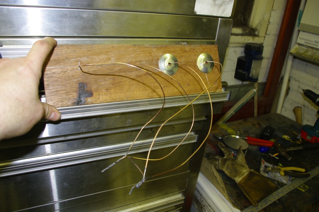
Following my plan I came up with this.

You can see that the merge points for both paired primaries are held together at the correct separation for the secondaries, by a short length of welding rod.

The washers are some 45 mm in diameter, and as the welding rods mark the centre lines of the tube, and are exactly the same length passing the washer along two side by side wires, allows me to check if the wires have the correct separation, to ensure the pipes wont clash.  Its a bit like the old fair ground game of passing a loop of wire along a wiggly path… if the wires touch the buzzer sounds.

I think no 1 might need a little more work, but generally I’m pretty happy with this.  So I’m going to take my model to AB Performance, to discuss with Andy tomorrow.

Incidentally, contrary to popular belief  I’m not actually going mad…. but the starter motor running in the wrong direction in my last post was actually correct.  Andy had given me one of the ones he uses on cars with  a prop shaft (Like a fisher Fury), these are reverse wound and so spin in the opposite diection.  So I’ll get that swapped tomorrow.

Posted in Exhaust pipes | Leave a comment

Sabre Engine Mounts, Gearshift, Steering and Reverse

I’ve not got too much done on the Sabre this week, as I’ve been focusing on the mini for a few days (which will be the subject of a separate update) and then just when I was ready to focus on the Sabre again, Kate’s road car shredded its timing belt and bent a valve, so I’ve spent most of this week rebuilding the top end of a Renault Megane engine instead of race car building.   With the Megane running again  (first turn of the key I might add :-) )   it was time to get on with the Sabre. 

But what I have done is complete the remaining engine mounts, complete the steering, and make a start on the gearshift and the reverse mechanism….. Can you tell I’m running a bit scared of making the exhaust manifold  and doing lots of other stuff instead ;-)

The last major mount to be completed on the engine mounts was the “support” leg of the front left mounting.   This needed  taking back from the mounting point on the block to the lower chassis rail.   Previously I would have put a pair of mounting ears on the transverse tube, and made a complex tube joint on the end of the engine mount.   But last time I was over at AB Performance   chatting to Andy Bates he suggested I did it with a crush tube and bucket bush instead.

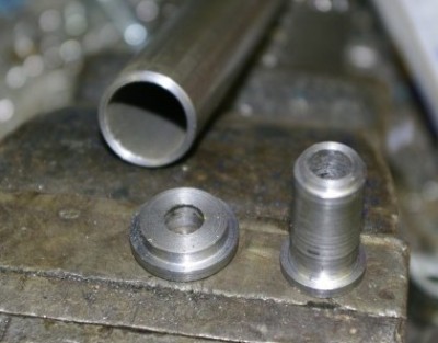
I’ve made so many of these in the last few days, my lathe is covered in a small mountain of swarf.  Obviously on the left is the small tube which will form the bush.   The small top hat section is welded into the end of the tube.   I’ve been asked if washers are good enough and the answer is “No not really.”  
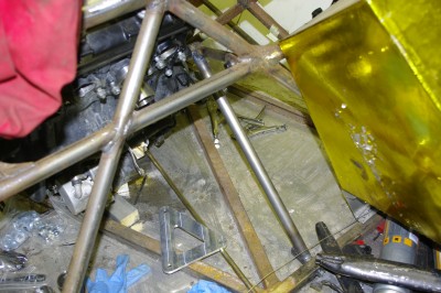
The tall component is the anti crush tube for the chassis rail.   The wider section at the bottom sits on one side of the tube, the tall section passes through, and you can see the shoulder on the thin end then supports the inside of the other wall of the box section tube. You then weld in both ends and you’ve successfully tied both sides of the chassis tube together.

In this photo the bush is in the bottom right hand corner, on the end of the  triangular right hand mount. As this triangle is pretty acute, I think I’ll put some bracing webs across the engine end.  
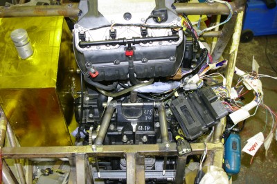
 

I also attacked the rear, upper engine mount, again bucket bushes and spacers were spun up on the lathe.  As this joint is very important in preventing the engine and the diff from trying to meet each other when the power comes on, I decided to use the leftovers of the CDS tube I used for the steering column.

The legs aren’t at equal angles because I needed to pick up on the existing anti crush mounts in the transverse chassis tubes.   I elected to use the original engine mount bolt, and also I spun down the original aluminium spacer.  

With the engine now solidly in place, you can see in this photo I was also doing a trial fit of the engine management loom.   The plan is to mount an ali plate on the rear engine mount, and mount the rectifiers here.   While I was doing this I also  mentally laid out  the coolant system.

Unfortunately, the coolant must exit the block to the right, as unlike the Honda CBR1000 engine the thermostat housing cannot be reversed. So unlike the other Sabres  mine will have the  coolant radiator on the right and the oil on the left.
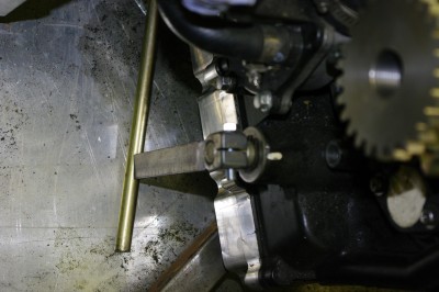
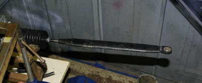
With the engine now nailed in place, I can start to think about the ancillary systems that connect to it.  The first of these is the gear shift.  Andy had provided me with a nice steel splined adapter, and so the first order of business was to weld on an actuating lever.  The plan is to use an actuating rod (seen here ) in the engine bay to try and avoid the issues that others have had with push-pull cables overheating and the shift becoming stiff to use.   The rod will connect to a push pull cable which will terminate at the firewall.  This brings me to the other end of the gear change mechanism… the actuating lever.
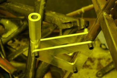
 

Unfortunately I have RSI/Carpel Tunnel injury in my wrists and this prevents me from using a paddle shift, so I need to fabricate a lever.    Now, in the old Genesis I had a habit of breaking the lever, because I’m a bit of an animal with my changes.  I also wanted to have a very short throw and that also added additional load to the short welds where the long lever met the pivot tube.  So this time around I wanted to avoid a long lever, not least because I’m trying to keep the passenger space clear of moving parts, to allow me to take passengers easily… I have an eager son who wants to get some track time in the Sabre :-).

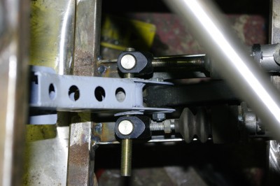
What this long preamble means, is that I needed to fabricate a pivot point for the lever in the front of the car,  after a bit of padding to position  me in a comfortable position, we worked out that it needed to be about 6 inches from the main vertical tube.   So we started testing it out using the front damper mounts as a makeshift templates.   These turned out to be perfectly proportioned. So back to the lathe to knock up some mounting bushes to weld into the vertical  tube, and voila we ended up with this. 
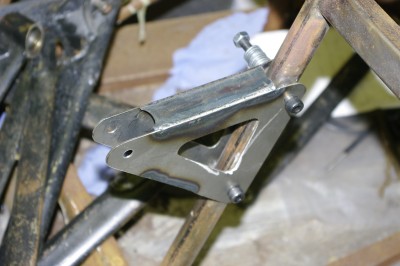
The plan is  to use a push/pull cable to come up the vertical tube, and connect to a lever attached to the handle.   This will then run down to the floor, and then run back to the firewall where it will connect to the activation rod that traverses the engine bay to shift arm.

But of course I can’t use my damper mounts for the gearshift, so I decided to fabricate the pivot mount from mild steel and I used the damper mounts as a template. We often fall in love with shiny shiny aluminium bits, but this 1.6mm steel component is much more rigid and very much lighter than the ali mounts.  It needs some reinforcing washers welding onto the main pivot points, but is otherwise complete.   I’m just waiting for the push pull cable, and then I can finish this who system off… which would be nice.   Its about time I started to get some systems completed, oh and those bolts may be a bit over long :-)

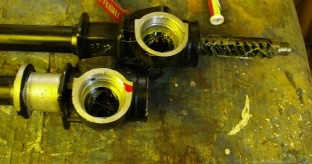
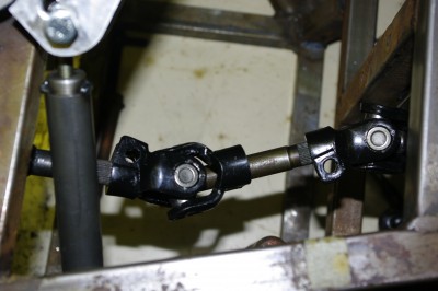
Talking of finally finishing stuff,   I span down the short steering shaft, and welded it into one of the steering universal joints,  to finally  finish off the bottom end of the steering column.   I used the old trick of dumping the joint itself in water to sink the heat away from the seals and stop the rubbers burning. Once it  was all fitted up I ended up with this.

 I think My cameras white balance was off BTW.  Hence the yellow cast.

 I have to admit to spending a couple of minutes spinning the steering wheel, and enjoying the fact that the steering rack moved in and out.   At last a mechanism that is working :-) .

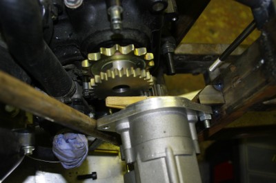
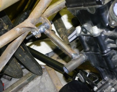
The next thing to report, in this rather long post that is covering a lot of  ground,  is that I’ve started mounting the reverse system.   Andy has provided me with one of the  ABPerformance reverse systems, which is basically composed of a geared starter motor, and a specialist drive gear.  You can see on the right of this picture that I’ve tacked in a mount at the rear of the engine bay.  The tube  on the left  was intended to connect to the right hand engine mount and the lower  tube of the rear engine bay chassis.  The plan was to weld a plate on this tube to attach to the free end on the starter motor.  

However, I’m having second thoughts as I think a turnbuckle connecting  that free hole on the left to the floor will provide a nicely triangulated, adjustable,  load bearing mount and save a bit of weight. This will also ensure the reaction forces are transmitted directly to the chassis.   But the front edge of this mount will need lateral location and I think the easiest way is to use a small plate to tie the whole thing to the engine, you can see a suitable bolt at the left of the drive gear  which is normally used to hold the chain cover on.   These chain cover mounts are often pretty weedy, so I’m not using them to hold the whole of the reaction forces, rather  just to tie in the motor and stop it jumping away from the sprocket under load. The clothes peg is there to hold the drive pinion out in the operating position, while I trial fit it all.

One odd thing though,  I tested the motor by shorting it with my spare battery.   Unfortunately, it ran in the opposite direction than  required and promptly unscrewed the drive gear from the output shaft with a clunk.  When it runs in the correct direction it runs the  engine in reverse and tightens the gear on the shaft.   I suspect I need a different motor, either that or I’m being stupid.  
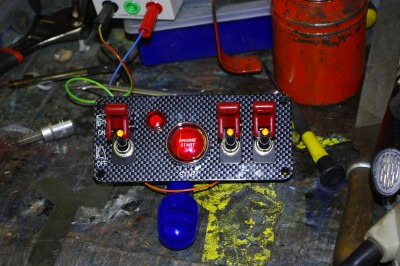
I’ll be buying the turnbuckle from those nice folks at McGill Motorsport, who today sent me this rather bling switch gear.   I bought it from them at the Autosport show, mainly because it was cheaper than buying the switches individually…. you’ve got to admit it is rather bling though!

Oddly those LEDs on the end of the switches are red in real life.

 And that just about brings you all up to date.
Posted in AB Performance Sabre, engine mounts, gear shift, Reverse, Steering | Leave a comment

Mini Progress

I promised that I’d keep you up to date on mini progress.  

I’ve taken three days off work to try and achieve a big jump forward on the mini.

I”ve recently taken the front subframe out, and stripped it down, and in the 4″ of snow a couple of weekends ago I degreased it ready for painting.

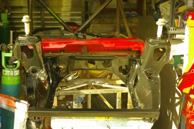
Here it is, slathered in a layer of POR15, two layers in fact.   It makes the front of the Sabre look somewhat over engineered :-) .

The plan is now to refurbish all the  front running gear, I’ve a big box of mini bits sitting in the corner.  I’m hoping to fit the engine to the frame and lift them both  into the car as a unit, rather than dropping it from above.  This is the way they did it in the factory.

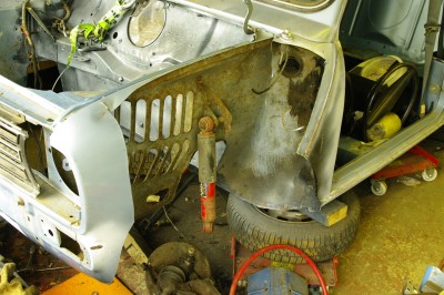
Today I attacked the front left wing.    T he wing has an ariel fitted and is also dented,  and I finally decided that it should be replaced, rather than patched.  The easiest way to do this is to simply cut the vast bulk of the wing out with an angle grinder.  What you then do is find all the spot welds, around the headlight mount, the front valence joints and the inside of the engine bay top edge.

BTW the lightly speckled bulkhead has already been stripped an POR15 painted, as I’m aiming to to repaint the whole engine bay before the engine is refitted.  The mottled effect comes from a light dusting of etch primer to give the next coats of paint a good key.   PO15 normally dries like glass.

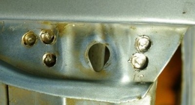
The welds are drilled out with a modified drill.   These are easy to make, you simply grind a standard drill flat at the end and them curve back the edges a tiny amount to leave a centralising pimple, and flat cutting edges.  Then you centralise it on the spotweld and “work it” around so the flutes cut in the edges, without the pimple cutting through the centre.   You then look for the line of rust appearing from between the two panels as the cut just passes throught the outer panel.  I also like wedge chisel between the panels to load the joint, so that it “pops” when the joint is broken.

 You can see  the process underway, on the 5 spots  at the front edge of the right hand wing.

 And in this picture you can see the oringinal welds drilled out across the top edge of the wing.

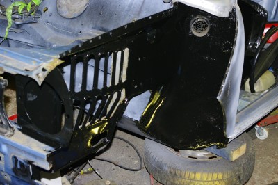
Here the complete wing has been removed, and the underlying metal work scarified and cleaned with some brass brushes in  a die grinder.   The new “A”Panel I fitted much earlier in this restoration is on the  right.

The the whole lot has been coated in PO15.  With the wing off it was clear, that it was the right decision.  The old wing, while not yet perforated or significantly thinned was, none the less in full on rusting to death mode.  With no protective  paint layer left and several layers of rust and scale present.  It would certainly have perforated in the next four or five years.   You can see that I POR15′d the whole of the wings interior, again this was beginning to show significant patches of rust that will only get worse.  I’ll leave this to cure overnight and then grind it back where I need to weld,  those exposed areas will get a layer of zinc weld-through primer.  If you expand the image you can see a small repair I made in the inner wheel arch, but other than that I’m pleased to report this panel was sound, the first time I’ve found a penal that is.  This gives me hope that once this wing is on…. the welding is done.


Posted in 1275GT mini | Leave a comment

Good Progress :-)

You know those days… the ones when nothing seems to go right, and you go out to the garage with a mental list of what you want to achieve…and 8 hours later you leave the garage tired and gritty but not having completed a single thing?

Well today was not one of those days.  I got loads done.

It didn’t start auspiciously though.  As I stepped into the garage it was -12 deg C and I was stiff with cold, and every bit of metal I picked up nearly took my skin off.   Enough of this! I need some heating, so I high tailed it over to Machine mart and bought one of  their little devil propane space heaters.   What a marvellous little beastie… it soon had the garage well into, not quite freezing territory.   Still on with the Sabre :-)

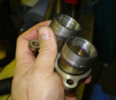
First up were exhaust headers, Andy over at AB Performance  follows my blog and is keeping track of my progress. So with the engine nearly in he thought  it was time I got on with the exhuast headers, and has sent me  the appropriate collars to fit the zx10, some laser-cut  bolt flanges, and some little step up conical sections that raise the exit port to 1 & 5/8″ in diameter.   Of course these needed welding together.  Andy recommended that I TIG the back edge of the mounting collar onto the tube. I feared this would create a stress point, but perhaps more importantly I feared I would burn through or at least sag through to the inside.  So instead I autogenously (no filler) welded the tube inside the collar and then dressed it back with a little subtle grinding using a small stone in a die grinder.  It didn’t take long and I was left with a small collection of what all the world look like stainless steel shot glasses.   I can’t say for certain ( as I didn’t check the fit before hand) but the welding has expanded the collars slightly so I mounted them using the lathe inside grip jaws and span a mm off  the exterior circumference. You can just see a slight depression inside the collars, but this is nothing major, and will not disrupt the gas flow, certainly not anymore than the edge that would have been present if I’d welded it on the outside.

With that job done, I moved onto to the  front of the car.  with the pedals now complete I wanted to get the brake pedal mounts welded into the car.  These are a couple of small lengths of 1/8 x 1″ x 1″ angle welded across the footwell.  It didn’t take long to cut the steel… in fact I also cut about 8mm off one leg of the angle to try and save a little weight from this chunky cross section. Then I MIGed it into place, and dressed back the welds underneath so that the floor plate will still sit flush. Coo we really are going great guns today.

You can see they are angled slightly, this is because I sit slightly angled in the car  as the chassis tapers, in fact the offset angle is about half of the  angle that the side of the chassis makes with the transverse cross members. Which I guess makes sense.

With the brake mounts in I could complete the front footbox reinforcing, so I cut, fettled in and then welded the top diagonal braces from 3/4″  tube.   While doing this I also notice a couple of tubes where all four legs of the weld hadn’t been completed and these got some sparky attention too. One of the top tubes is visible in the pic above.

We’re close to finishing the structural work at the front of the car, so I thought I’d finish of the steering rack.   I’d removed the little plastic bush from the non pinion end of the steering rack when I built it up, as these wear quickly.   I’d grabbed some phospher bronze off ebay, for the sum total of 12 quid, and knocked up a littled cylindrical collar quickly.   You can buy these from Burton Power for 15 quid + vat… but mine costs less and I have a foot of phosphor bronze for other projects  too.   Sorry I forgot to take a photo of it.

So I’m now running out of stuff to do by my feet, so its was on with the engine mounts.    Using Tim’s tube cutter I’ve now made both the top front mounts.

Basically this involved linked the bucket bushes that I made previously with some tube to the firewall mounts.  The process, is cut the tube, fish mouth the end, tack in place then remove from the car and TIG in place.  I need to do the lower leg of this triangular mount to finish it off.   Once both legs are welded on I think I’ll put a small reinforcing plate across the end.  The end of the bucket bushes will then be cut at an oblique angle to neaten them all up.

 I’ve been cogitating on the  rear low engine mounts for a while as they are basically in empty space.  In the end I decided to just keep it simple and drop another chassis member down to support a bush by edge of the right hand mount.  I can then run an M10 bolt in double shear.

I still need to do the left hand one. Which will simply be  a short section of 1″ box welded onto the double chassis member, with a drilled plate.

In this Photo you can also see the bucket bushes I’ve prepared for the upper rear mounts.  The one on the right in the picture is actually a threaded bush (m10 x1.25) to allow me to use the standard mount  bolt that came with the engine.

Hopefully, I shall have the mounts finished off tomorrow, and then it is on to the gear change.

Now despite the fact that I’ve spent all day in the garage and I know I’ve got stuff done,  when you stand and look at the beast it appears to be no different to the way it was this morning.   Its always like that at this stage of the build…. you spend all day working and at the end of the day, you have just one small, but perfectly formed bracket, which when you stand back you can’t see at all.  Roll on the day we send this beastie for power coating.


Posted in AB Performance Sabre, engine fitting, engine mounts | Leave a comment

More Progress

As Tim said in his comment two steps forwards  then one back, well today I was determined to make decent progress, and take more than 2 forward.

First up- was steering.  now that I’ve got  the steering mounts sorted out, it was time to attack the rack.  Andy had provided me with a brand new  2.4 turn fast rack.   He had also provided an empty escort rack casing  that had been spun down to fit the steering rack mounts.  So it was time. to transfer the internals from one to the other.  This isn’t a particularly hard job,  but it does require my largest adjustable spanner, which was over in the toolbox in the bus.  So after a quick jaunt to fetch it we got on with it.

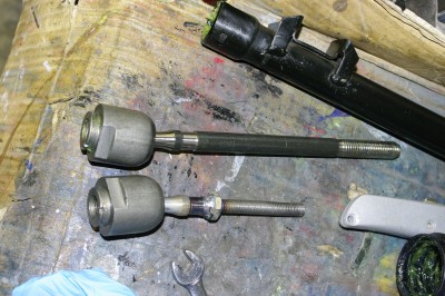
It isn’t a difficult job as you simply remove the shim plate, pull the pinion, remove one of the ball joints and pull the bar.  but it does mean you can get at the balljoints,  which is a part that requires modification on to fit the Sabre.  Basically the standard Escort steering arms are huge and are threaded about 11/16 unf,  they are also way too long.  I needed to both shorten them and slim them down in the lathe, then cut an m10 thread down the shaft.   This did mean I spent the morning on the lathe making yet more swarf.

Because of the difficulty in cutting a thread on the shaft when one end is a balljoint I actually cut 80-90% of the thread on the lathe, and then span an m10x1.5mm die down the partially formed thread to finish it off and clean it up.  I also span a nut down to the shoulder and welded it on so that I have an easy toe adjustment point.  This is required as the Sabre Steering arms do not rotate, being made of aero tube with a sperical bearing rather than a ball joint at the outboard end.  This way I know 1 full term – 1.5mm of toe out. 

Personally I’d have gone for a finer thread say m10x1.0  but the Sabre arms already have 1.5 pitch bosses in them.

Above  you can see the before and after, it did occur to me in the middle of all this  that this is still a huge lump of steel, and clearly ripe to be replaced with an aluminium clevis and 3/8 rose joint.  That’s a project for the future though.  

With both steering arms modified I reassembled the rack and mounted it to the car.  At last we’re getting close to having at least one system completed.   The only thing left to do on the rack is fit a bronze bush to the non pinion end, I’m waiting on some phosphor bronze  bar stock before I can spin one up, and then I can close out the steering rack.

So flushed with success I took my life in my hands, and welded the quick release steering boss to the column…. this I’m glad to report went pleasingly well, although I might shove a 4mm roll pin through the joint just for extra safety.

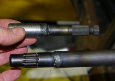
With the welder out I thought I might  as well crack on with the other end of the column.   This required sleeving a short splined shaft, welding on an intermediate collar, to step it up to the inside diameter of the column.   The shaft is actually welded at both ends.


 With the rack in place I could finally mock up the intermediate shaft that I”ve worked so hard to get into the steering system.   The offset isn’t huge, but it is present, and the installation should be  much safer as a result. SoI’m quite pleased,  I’m just waiting on another short length of splined shaft and then I can complete the lower end of the steering installation, I can’t cut down the main steering shaft until the pedals are finished as they drive the whole feet, arse, hands, wheel relationships.  So best crack on with the Pedals then….


Besides, with temperatures in the garage approaching      -4 deg c the thought of being hunched over a hot welder for a couple of hours is pretty attractive.  

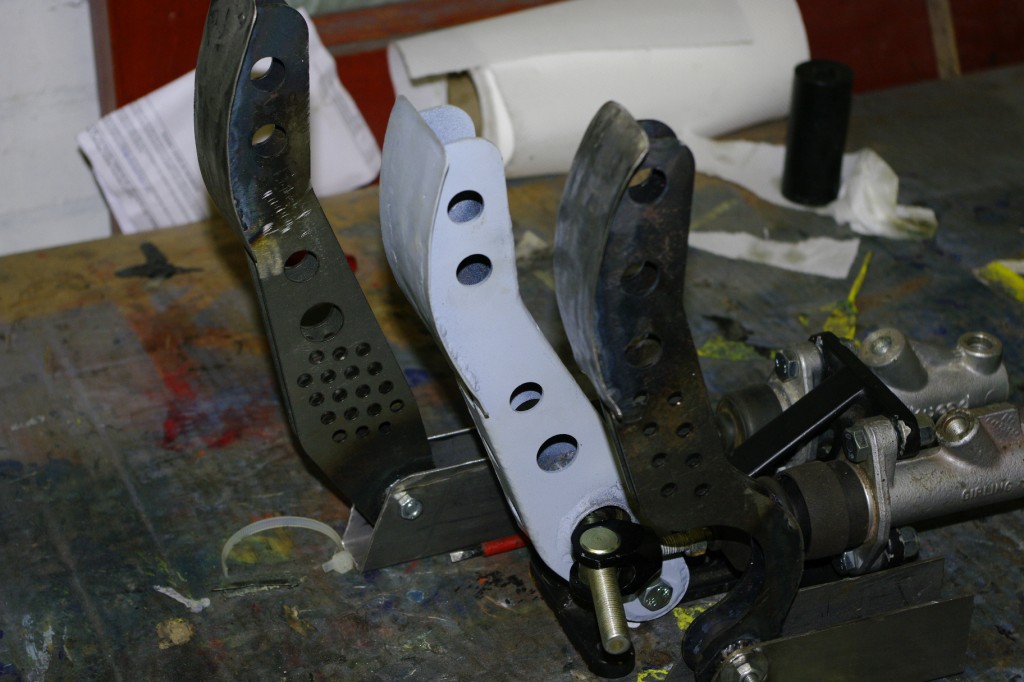
The brake pedal, was done a while ago, so it was time to focus on both the accelerator and  clutch….  not much really to show you here except the finished articles.  The clutch is sitting on a temporary base which I just knocked up quickly for the photos.  Incidentally,  the pivots on the clutch and throttle are higher as the brake pedal will be mounted on some 1/2 x 1 inch box, whereas the other pedals will simply be bolted to the 2mm ali floor panel.   These aren’t yet complete as they need  a return spring, a travel limit screw and the rear rotating quadrants to attach the cables, but they are certainly finished enough to bolt temporarily in the front floor areas and start finalising the ergonomics.  Plus I proved to myself that I can still weld :-) .   With that the snow was falling quick and fast, and the home made pizza was calling so I called it a day.  But several steps forwards today :-)


Posted in AB Performance Sabre, Brakes, Steering | Leave a comment

Sabre Tooth

So with only half a day to work on the Sabre last weekend I’ve only got a small amount of progress to report.

Basically, we got the engine  and diff fully aligned   this is always the critical issue because misalignment = chain jump or at very the least excessive chain wear. as usual it needs to be done in three planes.

Longitudinal alignment is done by dropping some thick wall Ali u shaped channel over the driver and driven sprockets and verifying the gaps

Relative axial alignment, is done by clamping a vertical straight edge  to each of the the sprockets and sighting across the gap to see if it tapers.   We also checked both the diff and driven sprocket with a digital inclinometer and they were found to be within 0.2 degrees of each other and vertical in the chassis.   Lastly we measured from the center line of the inlet cam to the main bulkhead to ensure the engine and crankshaft line was properly parallel to the transverse bulkhead.


When all three measurements were correct, we could start fabricating the mounts.  First job was to make some bucket bushes to fit the mounts on the block.  Firstly spin up a little top hat section to fit across the end of the tube we’re using then Tig weld it onto the tube.  Bolt this to the block.

Then make up the mounting tube to fit the mounts on the bulkhead.  These were fabricated for 1/2 bolts which are frankly massively heavy and vastly over specified. So I knocked up what were essentilly double ended bucket bushes, and some little top hats to fit the brackets, to convert to 8mm bolts.  All of which took ages… and to be honest I’m not very impressed with the result, as for some reason the 8mm holes up the middle of these components is rattling a little on that test bolt… which incidentally might be a little over long too. Tim also Kindly pointed out that it might well have been easier to fit 12mm bolts with a 6 or 8mm hole up the middle.

To be honest the whole set of engine mounts are turning into a bit of a nightmare.   The rear mounts are simply in free space, and difficult to triangulate  and the front mounts are a mess…. about the only thing that’s any good from this morning’s work is the bucket bushes on the block… Pah… I need to leave these alone for a while and look at them again with a fresh mind.  Chatting with Andy, he also suggests that before I complete the lower stays of the mounts I need to build the exhaust headers to make sure I have the routing right and its a lot easier  to do without the engine mounts in the way.  So  in time honoured fashion  I’m walking away from this job for a couple of days.

So on to an easier job.   The steering rack fits in the nicely made ally mounts, unfortunately the rack supplied was slightly undersized , and actually rotated in the mounts.  To  correct this I simply mounted the caps from the mounts in the lathe and span about 1,2mm off the mating faces.   This closed up the aperture, and when bolted up clamped the rack nicely in place, so at least some good progress to report today. Next step on the plan to a working steering system is to build my new quick rack into the fitted casing, as part of this I also need to fit some bronze bushes.

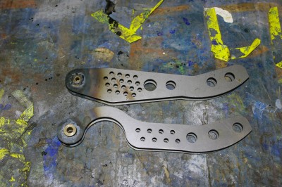
In the evenings, I’ve also mostly made up the clutch and throttle pedals.  These are made from the blanks I had laser cut in January, welded on to a centre spindle that I knocked up in the lathe.  The spindle is drilled to take some Oilite sintered bronze bushes and a 6mm spindle.

I’m not too pleased with these either.  the colour indicated that I over heated the steel…. Pah   Functionally they are fine…. just not made a well as I hoped


Posted in AB Performance Sabre, Diff, Diff mounting, Engine, engine fitting | 1 Comment

Mini News

Kate and I had a ball at the 750MC awards dinner, last weekend which meant that garage time was somewhat curtailed, as we hopped in the car quite early on Saturday and headed off for a night on the tiles. :-)

Like the Autosport show marks the start of the new season and re-fires the enthusiasm, the dinner reminds us all that we’ve only got about 8 weeks before the new season starts in earnest.  All My RGB mates were chatting about their winter plans, and whether they were on track against plan, and there was me thinking…. “I’ve got an awfully long way to go”. Gulp

Lots of people commented on the blog and asked about the Sabre, but  they also asked me for a bit more information about the mini. So here’s a bit more info and I’ll start  future updates with a paragraph on the mini.

Firstly its a 1979 1275GT mini, which I bought Kate for Christmas last year.   Its the same age and model the she was driving when we first met and she dearly loved it then. Well, two babies came along, and  it ceased to be practical. It slipped into rusty old banger territory and at that time I didn’t have the tools, money or experience to maintain it,  so we sadly parted with it. Last year, with the Kids grown, I found an  identical car (except this one is blue and the original was red)… even the interior is identical.  Genuinely 2 lady owners, 45,000 miles and used to drive to the shops and back for the last 10 years.  (circa 200 miles per year acording to the MOT certificates).  It seemed pretty sound although the front wings and A panels were perforated.

Driving it home proved that it was straight and the engine was pulling well, so we were pretty happy and Kate had a huge happy mini grin when she got out of it :-) .  The original plan was to do the wings and A panels, give it a quick re-spray and get it out for last summer, thusI started work on it last Easter.  Unfortunately that deadline came and went in the wake of  finding the need to weld in 2 new wings, 2 new inner panels, 2 new A posts. 2 partial flitch panels, 2 new door skins, 2 new outer sills,  2 partial inner sills, 2 new floors and 2 new rear boot floor corners, 2 rear wheel arch segments,  2 rear subframe mounts and 1 new rear valance.  So you can see that the welding got a bit out of hand   But we’re on the home stretch now. :-)

The current status, is that the welding is all done bar fitting one front wing, and new rear seatbelts mounts (which weren’t originally fitted anyway).      The shell is now very sound and the complete rear subframe has been removed, painted and refitted, along with all new brake pipes, new suspension cones, new A arm bearings, new brake cyclinders, and new dampers…. well basically everything is new bar the major castings.   

I‘m currently working on the front subframe and engine bay.  Some numpty in the past has spilled brake fluid all over the front bulkhead, this had lifted the paint  and was merrily turning the front bulkhead to dust.   It only surface pitting now, but in 5 years it would have been a latticework of doom.   So the engine is currently out, the front subframe is sitting on the floor, awaiting removal of 30 years accumulated grot and then the full renewal treatment.  Current objective is to get it back on it’s wheels and ready for painting around the end of February.   Lets see if I can hit that deadline.

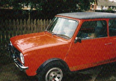
So a couple of grainy pictures. of the old  (complete with youngsters who are now aged 20 and 16)


TheThe to-d0 list before she is sent off for painting  currently consists of.

  • Fit and paint 1 new wing
  • Weld in new seatbelt mounts
  • Smooth off all external welds
  • Paint and refurb front subframe and all front suspension components.
  • Prep and paint engine bay.
  • Change clutch, water & fuel pumps on engine
  • Paint engine
  • Refit engine to subframe, and subframe to car.
  • Replace all control cables
  • Replace cylinder head with one with unleaded valve inserts
  • Remove all glass, and remaining exterior and interior trim, door locks etc
  • Clean and paint 50% of underside
  • Seam seal all new welds
  • POR 15 all external seams and seam trim interior edges.

Which in itself is quite a long list…. hmm

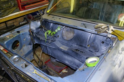
Here’s a picture of how she currently looks, the bulkhead has just been painted with PO15, and the subframe is stripped and sitting on the floor awaiting attention.  I’m currently awaiting a huge box of mini bits.


 e

Posted in 1275GT mini | Leave a comment

Diff Baking.

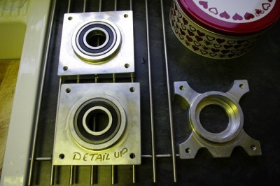
Oh!  you’ve just caught me completing a bit of baking :-) .  Andy advised that trying to fit the diff bearings by press fitting them alone would likely end in disaster, so the best approach was to use heat and cold.  Essentially I stuck the diff bearings (LJ 1-1/2 2RS EU if you’re interested)  in the freezer at -18 deg c for 48 hours, and the aluminium housings in the oven at 250 deg c for 30 minutes.   Extract both from their thermal lair and the bearings literally just dropped in the housings indeed they dropped so easily they landed  with a clang,  so the day got off to a great start. After that it went down a hill a bit and I didn’t get as much done as I had hoped.


BTW on the right is the new version which Andy lent me so that I could machine my ones (the ones on the cooling rack) to the new light weight pattern.   TBH life’s to short to spend hours unnecessarily spinning the handles of a milling machine, so I shall just buy a couple from Andy later in the build. Apparently they save .75Kg per side.  But for now I’m going to use the v1.0 ones to get on with the build.

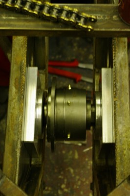
First up, Duncan and I fitted the bearing to the Quaife  Diff, using the time honoured method of using a specialist bearing driver and a large hammer.   As usual the specified bearing driver was a very large socket that matched the size of the inner race.  Once the bearings were properly home on the shoulders of the QDF7ZR,  we attempted to fit them to the diff slides at the something  back of the Sabre.   Hmmm, it seems that something is amis,  the combined width of  2 diff mount blocks, 2 sets of bearings and the diff itself was 5 – 6mm wider than the distance between  carrier plates in the chassis, further when we measured the front of end the chassis we found the gap tapers by a couple of mm too.  So…. we had a cup of tea and a chat.  Eventually we re-measured and found that the gap where the diff carriers actually sit was mostly parallel but we still needed to lose 4mm  off the combined width.  So there was nothing for it but to remove the diff from the carriers, chuck them up in the lathe, and face them back by 2mm each side. But, before I could do the carriers I first had to spin up a proper pusher to allow the bearings to be pulled from the diff.  So there then followed a good couple of hours making swarf until finally, after two further trial fitting cycles and a bit more twiddling on the lathe.  I had a diff fitted into bearings, bearings fitted into carriers, and the whole lot fitted in the chassis…. yay.   :-)   some days I wonder why I invested in a lathe.  Today was not one of those days.


Now the reason I started the the  job of fitting the diff  was actually to start fitting the engine.  To do that you need to align the output sprocket with diff sprocket, so obviously having the diff properly mounted is step 1.

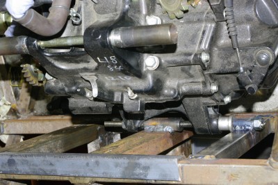
Step 2 is to get the thing in line, and then start fabricating engine mounts.  Duncan  and I manhandled the zx10 around and eventually worked out it’s rough positioning.  With  free movement in every plane, its a right pain to get anything set, so we eventually focused on the rear lower gearbox mount.   As you can see from the  photo below, the gearbox wants to be mounted in free space (don’t they always.) 

I have to admit I am slightly concerned that the output sprocket seems to be perilously close to the left hand chassis rail.   I’ll need to order a chain wheel, sprocket and chain get them fitted in order to check that out though.   I wonder if the slimming down of the bearing blocks has adversely affected the clearance.

So we eventually decided to mount a threaded boss on the upright section of the chassis, in front of the diff carrier.  This has the advantage, that you can adjust the left/right alignment of the rear of the engine and hence the output sprocket by using nuts on a long threaded rod, and when happy these can be replaced with permanent spacers of the correct size, and the rod swapped with high tensile bolts.

The eventual plan is then to fabricate a mount on the “other side”of each gearbox lug, and then the bolts will be in double shear. These will probably go down to the 8mm bosses in the lower chassis rails (you can see the top one in this picture.  So more lathe spinning ensued making a threaded boss, which we then flatted on one side and welded into the chassis.


I’ve also completed the brake pedal,  it did take a bit of lapping using, a lathe, a broom stick and some grinding paste to remove the high spots from the bearing tube, but otherwise I’m quite pleased with how it has turned out.  It looks and feels pretty sturdy, and is only marginally heavier in steel than the original Wilwood aluminium cast pedal.   It just now needs a top coat of paint (silver I think) and some grip tape on the pedal section. Here it is in a coat of etch primer. 

Now I just need to work out how to mount the clutch and accelerator.

Oh and I’ve also drilled the chassis for the steering mounts, I need to knock up some 8mm bosses to weld in to prevent tube crush, after that I can start work on the steering column proper.  So all in all a fair bit of further progress.  Still a long way to go though.


Posted in AB Performance Sabre, Diff, Diff mounting, engine fitting, engine mounts | Leave a comment