Wheels on my Wagon! .. well 2 at least.

Stop press.  This car will move!…. well at least it would if I hitched it up onto its right hand side Dukes of Hazard (or if you’re under 40 Fast’n’ Furious) style, as it currently only has the right hand wheels.  But, wheels it does have, as you can see from this rather dull shot of a tyre.

Andy phoned me last week, to let me know I could come and collect the suspension , uprights hubs and disks. This was somewhat quicker than expected, but it appeared Lee had had a nasty biff while testing his car and had written off his chassis courtesy of an errant classic mini driver who had tried to park his A series engine inside Lee’s cockpit.    Lee thankfully wasn’t hurt, which is all credit to his Sabre’s chassis which has now sustained three massive hits all of which the driver walked away from. But  like all good bodyguards the chassis put itself on the line to save the occupant and it was a write off.

However, because of the narrow angle of attack of the mini it had gone completely between the suspension units, and these were  undamaged.  Unfortunately Lee is out for the season awaiting a new chassis, so Andy has agreed with him that I’ll have the running gear, and Andy will sort him out when the new stuff arrives.  At least that way one more Sabre gets out on track.  So heartiest thanks to Lee for allowing me have his hardware… but hearty commiserations too for his run of bad luck.  I did however feel a bit of a vulture stripping the wishbones off his bent chassis. :-| .   In addition Andy, poor chap was hobbling around with a duff back, so I hope you both get well soon.

So this left me with a full set of suspension for the four corners which should in theory bolt straight on to my chassis mounting points, and while I was there I also collected a couple of bits of additional bodywork, which I was awaiting.

Back home with the running gear, I made a mental list of what needed to be done to get the car rolling,  well obviously I need all four wheels, but this is currently impossible as the car’s left hand side is tight up against the garage wall.  So I elected to fit all the right hand gear first, then manouver the car around so I can concentrate on the left hand side and this will also allow me to access and fit the water radiator and coolant system which is the last major part that is missing in the engine bay.

To do this there were a few things on the to-do list.  Namely; complete  the side pod floor supports, fit the side panel, grind the powder coat of and reweld an incomplete joint (allways a pleasure GRRRR). Fit one last bit of cabling in the wiring loom for Lamda sensor, and then sort out all the dampers and push rods.

The floor supports came first and I used the simple approach system that I used on the old Genesis.  Namely a thinwall  1/2″ steel tube, crimped in the vice to form a flat at each end, and then bent and drilled  to the correct shape  to support the floor at the right level.  The floor was supported on a 2.5m spirit level to ensure it was lying flat and then these were just bolted to the threaded bosses that I welded into the chassis way back in March.    Andy I know makes adjustable supports with a 6mm rod, threaded M5 at each end, and 2x M5 rose joints, I thought this looked like a lot of work, so we’ll go with my bent tube approach for now. As before it resulted in a pretty rigid installation, which will firm up even further when I fit and bond the bodywork parts to it.

Next onto the side panel, this is an incredibly thin, moulded GRP panel that fits the contours of the tubes at  side of the space frame. It appears to have been made from a single layer of chopped stand matt bonded with less resin than I usually have clinging to the sides of the pot when I’ve finished my GRP moulding.   Don’t get me wrong its perfectly made, and properly impregnated, just incredibly thin and light, and away from the car it’s quite floppy and in danger of tearing itself apart under its own weight if held horizontally.   This is appropriate as its only real purpose is to keep the rain off me.   The exterior bodywork itself does a good job of shielding the wheel arches, and as empirically proven by the Lee the main chassis tube is incredibly strong without the need for cladding it in Aluminium.  Plus it would be a very difficult shape to do in ali anyway.   On other cars Andy has previously bonded these panels  in place with Tiger Seal, but on his advice, mine is just held on with a couple of self tapers, cable ties and some large head 1/8th rivets.

So on with mounting the wishbones, brakes and wheels…. starting at the back.

Unsurprisingly the wishbones just bolted on at the inboard end with no trouble, and the brake calliper bolted straight on at the outboard end.  Here you can see that rear wishbone has a rear toe link, and a pushrod to drive the inboard suspension.  Toe and camber are independently adjustable by shims and that toe link. You can also see the 6 drive studs which take the lobro CV joint.

However, when attempting to fit the wheel a few things became instantly apparent.  The Wilwood powerlight handbrake mechanism will not fit under my 13 inch wheels, and the callipers just foul the interior of the wheel spokes when bolted up tight (1 or 2mm).

The first problem can be surmounted by removing the hand brake actuation arms, I’ll just have to come up with an inboard handbrake mechanism instead and I know Andy has a working prototype on Lee’s car anyway.  The second has two potential solutions.  The first is easy… wheel spacers.   Lee was already running some thin ones, so I’ve fitted some slightly thicker ones to get the clearance.  When choosing wheel spacers you should always choose the properly engineered ones with a central socket and spigot that properly engage with the central spigot on the hub, and the corresponding aperture on the wheel.   This is important, because the spigots both centralise the wheel properly and transfer the car’s weight to the wheel’s centre.   The bolts should really only provide additional clamping pressure and support, not the primary primary load bearing mechanism.  I get mine from JJC racing on ebay, mainly because I can’t be arsed to do the two hours work per side that it would take to make them on the lathe.

The second possible option is of course to get some new wheels, these are my 6″ rims which where the largest allowed when I bought them.  RGB now permits 7″ rims, so the obvious thing to do is buy a suitable sized set of 4  7″ rims, and use all my 6″ on the front,  thus giving me a complete spare set of wheels and tyres.

At the inboard end things required a bit more fettling,   the aperture in the bell crank is quite narrow, and this was forcing the rear of the damper upwards, as the mounting eye bound up in the crank. The natural rest position for the damper was with its tail end about 1.5 inches in the air.

I could just about force the rear end down to the mounting bolt, but this is obviously undesirable from a suspension kinematics perspective, and would clearly side load the seals in the damper internals and damage them in short order too.

So I knocked up some little ali spacers on the lathe, and you can just see these under the rear suspension mounts.  These raise  the damper up and I think solve the problem, but I will need to check again once the car is on its wheels.

Talking of the Lathe, the more observant among you will notice that the damper is mounted with little M8 bolts, “but Dampers typically have 1/2 rose joints for mounting, they’ll be rattling about” I hear you say.  Of course you’re perfectly right and it was necessary for me to stand at the lathe and knock out some little  tapered spacers to both support the damper in the mounting slot and convert the bore to 8mm.  This was also true of the other end of the damper and the pushrod extended rod end.   Incidentally that seems a little loose, so I might have to take it back to Andy to get it re staked to tighten it up.


Anyway here’s a selection of yet more widgets that form the spacers, and represent about 40 minutes work.   It doesn’t take long once you’ve sharpened the lathe tools and got the hang of it. These are just out of the oil blacking bath so are still nice and shiny.

Oil blacking, gives some degree of corrosion protection, and if your interested is easy to do for small parts.

Hang the widget from a wire and heat with a blowlamp until it reaches the blueish stage… then drop into your purpose built oil blacking bath.  In my case an old bake bean tin filled with old engine oil.
Retire to a safe distance, or carry it outside while coughing like mad as it produces “a quantity” of white smoke.
Leave to cool in the oil.
Remove and admire the finish.
Oh and remember that the oil will also have been heated by the hot steel. So be careful when you move it.  (ouch).  I really must buy one of those home passivating kits some time.


Anyway next instalment…. the front suspension.


Posted in AB Performance Sabre, damper, handbrake calliper, Suspension | Leave a comment

Cough cough, splutter…. cough cough Grrowwwwlllll :-)

Well its been about a month since my last post, but despite my tardyness on digital reporting, I’ve not been idle.  I’ve been steadily driving forward towards to the magic moment when the beast bursts into life.  You may recall that I’d taken delivery of the bodywork, and that this allowed my to finalise the exhaust position.  Basically this involved orientating the last bend into the can, cutting it and welding it on to the end cap, so that the other end of the exhaust exits through the pre-existing hole in the side pod.

After that I drilled the joint and welded on the Lambda sensor boss.   All of this takes a lot less time to describe than it does to to do of course and completing the exhaust represents about a full weekends work.      The Y piece is also adorned with a couple of  eyelets for the tension hooks that hold the whole thing together, obviously there  are matching pairs across each joint a total of 6 springs all together.

Those little M5 Cap head bolts around perimeter of the can are to allow me to disassemble it, and re pack it… which is an all to frequent practice.

At the other end of the Can is a slip joint, which I’ve  welded into the end cap,   The slip joint is to allow me to fit  the MSA Mandated Catalytic converter, which I’ve cut from the original exhaust that came with the zx10.   This is currently over long and I’ll trim it back to a much thinner slice of cat once I have the bodywork in place to get the line.  The idea of the slip joint, is so that when I don’t need the cat I can simply pull it from the Can and replace it with a standard exit tube.  If you look carefully at this pic, you might  also see that the  far edge is not circular as I’ve cut it back to clear the bodywork, and there is essentially a segment of the circumference missing and capped with a flat plate.  With the addition of some heat wrap to the headers and few minutes struggling to get at the bolts, the exhaust system fabrication is complete, although I think I’ll also wrap the remaining merge collector too.

Now, if you look at the photo you can see some high pressure oil pipes, traversing each side of the exhaust…. these obviously need to connect to something, and of course that is the oiler cooler.

 Here it is sitting on the new floor that I made from the templates Andy supplied…. You can see it is currently making a handy shelf :-) .

The floor is made from  1.6mm  T6 tempered  aluminium which I bought as an 1.2 x2.4 m sheet. And I have to say it is very tough stuff, particularly as it broke my favourite air nibbler.

The cooler itself is a heavy duty unit, as RGB experience is that these are less susceptible to the stress fractures, that cause leaks and blown engines.  It sits on a small plinth that lifts it up to the correct height for the duct in the bodywork.  If you’re interested in the details, it is a 25 row, 235mm matrix with dash 10 AN/JIC fittings.

The neat little plinth, plus the stabilising bracket on the left,  made from an off cut of that  indestructible side pod floor, are of course the work of sheet metal master Duncan.   BTW for all my RGB mates who’ve asked about his crocked knee… the MRI scan shows inoperable patella cartilaginous damage… but it is improving with the help of a petite & pretty physiotherapist… which I’m sure would help most conditions :-) .

So all that remained to complete the oil system was to fit the oil temp sensor that doubled as a sump plug, unfortunately this wasn’t as easy as I’d hoped as the sensor used an M12 x 1.5 thread, and the sump has a M12 x1.7 port.  0.25 makes all the difference.

By now I’d completed all the rest of the system, so I didn’t want to tear it apart again at the front of the engine to make a temp sensor port, so my only option was to make a widget.

Now I occasionally get asked questions like, “Why do you do the racing lark, its expensive, time consuming and you don’t win anything”.

Well the reasons are many-fold,  it is something to do on my Saturdays, I love being in the paddock with my buddies, it forces me to test and stretch my Myself in the car and I lean new skills of all types… BUT… its also about the pride in making something with your own hands, and nothing embodies that better than  making a widget.

This little bit of steel  ( Not aluminium or brass because they crack and fail) has an M12 x1.75 male thread on one end to go in the sump, and an M12 x1.5 female port on the other to take the sensor, and a hole up the middle to let the oil bathe the sensor.  I made this out of a solid piece of hex bar.   I used my hands and eyes, and 10 tools.  (lathe, M12 tap, M12 tap handle, M12 die, M12 die handle, centre drill and 5 .5mm drill, and Hacksaw, fine file and vice ).

It was conceived in my mind, and made real by my hands… and it fitted perfectly into the parts made super accurately, by computer driven machines.   There a certain pride to be derived from  making something really well, even if it will be buried at the bottom of the engine bay and hardly ever seen again.   That’s the satisfaction and glory of the widget!

Anyway it fitted perfectly, and I’ve wound it into the sump port, and locked it in place with an appropriately place jubillee clip.

So the oil system, and exhaust systems are complete…..Excellent,   what’s next?

Well I need to test this engine and actually get it running,  the only things I now need to do before I can hit the start button is to fill it with oil, and make sure the electrics are complete.   It doesn’t have a coolant system yet…. but I can run it for a brief period using just the oil alone to cool it.

The ignition  circuits have been complete for a while, but I did spend a few hours giving the dash wiring a final clean up.  One thing I did need to do was to mount the regulator, and complete its connections.  These cables aren’t yet properly tied down… but the wiring is complete.

So with the oil circuit complete, the necessary engine management cabling complete, and the alternator properly plumbed in…. I’d run out of excuses.   It was time.

I filled the engine with oil, and as both the oil cooler and new filter were empty, I manually filled the cooler before fitting the hoses.  Then in the time honoured tradition I removed the plugs and span the starter on the battery to get some oil pressure.  This illuminated the first problem…. the ultralight lithium battery goes flat pretty quickly if the engine doesn’t start at the first turn of the key.  So I’ve decided to replace it with the normal lead acid type and (at least initially)  take the hit in weight for improved starting reliability.  I jumpered in a support battery and continued cranking until I got pressure, then I refitted the plugs and stick coils.

Now there really are no excuses!

First lob in a few litres of unleaded fuel, connect the fuel pump, and run the ignition cycle a few times to charge the fuel rail.  Check for  leaks… we’re ok?   Then hit the start button.

There followed a few minutes of coughing  and non starting, as I think, the injectors got charged, and re lubed by the fuel, then she fired, at first running on a couple of cylinders, then 3 and four kicked in and she ran properly.   Once running each restart was much less hassle, but without a cooling system I couldn’t let her do much more than run for 30 seconds each time.  BUT  she  is running, and that means that I’ve manged to get every one of the 1000 things in the critical path to this point done correctly.

A  major milestone has been reached, and I pronounce my self  ”Most well chuffed”.  So chuffed in fact that I rang Dunc and Tim to let them hear my engine running for the first time.   They must think I’m a nutter.


Anyway by way of proof here’s a shot of the Dash4 Pro.  In the top right corner  where it says 1302…. that’s the engine RPM.


Posted in AB Performance Sabre, Engine, Exhaust pipes, Fuel | 1 Comment

Tiger Tiger Burning Bright

If I might quote William Blake, ” Tiger, Tiger burning bright, In the forests of the night, What immortal hand or eye, Could frame thy fearful symmetry.”   Although I guess Blake didn’t have to work on his focus like I clearly need too in the pic right, although given that age’s penchant for laudenam, things might have been a bit fuzzy for him too

Anyway, I’m waxing lyrical, because the more observant of you may have noticed that this particular Sabre tooth tiger is attached to a chunk of red bodywork.  Which is great news.  Andy dropped it over one evening last week, and I arrived home to find  the components parts of an AB Performance Sabre sitting shining nicely in the sunlight on my driveway.  It now sitting in the tall grass, looking menacing, and indeed it does have a fearful symmetry.   It’s also incredibly low, and rather long.  We’ve measured it and I think I have about 4″ free, lengthwise, in my garage for it.   I suspect I’ll need to engineer an easily removable front or rear panel so that I can walk around it in the garage.

You can see there’s one or two bits missing , like the bonnet, which I’ll collect from Andy next week, and also that this is second hand body work, as its carrying Lee Baverstock’s name.   In fact I think it’s third hand as at least some of this  (the side pods and rear tub I think) were on Richard Wise’s prototype Sabre in its first year of running, and which Tim gently rearranged using the front of his Fury halfway round Clearways at Brands hatch.  It’s going to look great when I finally get around to painting it my now traditional Subaru blue. Although in fairness it looks great now.   I will have to move it though for when Kate wants to hang out the washing.  I bet Adrian Newey doesn’t have that problem :-)

Anyway, the reason I’m pleased to have it, is that I needed the floor profiles to finish off the  exhaust system.  Before I started though, Duncan, Duke  of Limpage, and Lord High Protector of Crocked-Knee turned up on Saturday morning to be installed in his normal position on the throne of tyres. Kate and I administered the now traditional offering of a bacon Sarnie and the weekend’s work commenced.

The exhaust sits inside the the right hand side pod, and I needed the floor profiles to make sure that I could position the silencer can correctly within the pod.  From the position of the exhaust can, I could  then work out the final routing of the secondary exhaust components.

You may recall that I’d built the primaries back in the spring, but stopped the system just after the merge collectors, so now I could crack on and finish it.  Andy’s magic length for this section of the exhaust is  ” As short as humanly possible”.  Hence the 4-2-1 section is pretty compact, the secondary merge collector is sitting on two short lengths of connecting pipe TIGed onto the individual primary collectors,  So fitting this bit took a fair amount of trimming  and fitting of partial 90 degree  bends cut at an oblique angle to get the edges to line up, the curves to fit, the lengths the same,  the tubes parallel and correctly spaced to slip in the merge collector.  Not easy. But eventually we got there, and the secondary collector is a firm slip on fit.

All I need to complete the system now is a 45 degree bend to feed into the can, and an exit tube out of the can.  This is where  I’ll mount the stupidly mandated slice of Catalytic converter that the RACMSA require to please the green lobby.  I can’t help but think that pumping out palladium and various other heavy metals by fitting a catalyst  to an engine that was never designed for one, is a very bad idea.  Much worse than a bit Carbon Monoxide.

I’m currently in two minds as to whether or not I should weld the secondary and primary collectors together, to form a single unit. However, experience has taught me that trying to fit 4 primaries into a single 4 way rigid connector is bloody hard work… so I may elect to join all these units together with tough springs, but I’ll ring Andy in the morning and see what he thinks. You can clearly see that my welding is nowhere near as good as Andy’s… lets hope it holds together.    Also in this picture you can see the red -10 JIC hose fittings for the oil cooler take off adapter , so it seems my previous modification of the take off unit has been successful, as they both clear the exhaust system by a reasonable margin.

Now talking of inputs and outputs… I’m pleased to report that I’ve finished the fuel system.  The fuel tank is clad in a couple of square meters of insulating NASA style space blanking to protect it from the engine bay heat, and the output hoses are all routed, fixed in place, and again heat shielded.  The connection to the main fuel rail is via the OEM connector , at one end, and by a JIC -6 connector at the other end.  This in turn links to a quick release, dry break fitting, that will serve as a fuel dump connection, and coincidentally also used the RACMSA mandated fuel sample valve.  No one else seems to bother with these in club motorsport, but just recently a few people have been fuel sampled, so I guess I ought to fit it.  Also it will be handy to be able to easily dump out the fuel and it will provide a handy point for testing fuel pressure. To this end I’ve also fitted a pump override switch in the engine bay, so that I can flip on the pump independently of its normal control via the ECU.

SO with exhaust 80% there, fuel done, electrics done… I only need to work on completing the oil and coolant circuits and this baby will be ready to run in the next couple of weeks. cool :-)


Posted in AB Performance Sabre, Exhaust pipes, Fuel, fuel tank | 2 Comments

Two Out of Three Ain’t Bad

Right, I’m beginning to feel that I’m on the home run with this car now.  However I’m still very jumpy about making the meeting @ Anglesey in early August.  Unfortunately,  my loyal  Chief Pit Monkey,  Duncan has monumentally crocked his knee, and is hobbling around on crutches pretty much unable to do much. Given that my garage is basically a large collection of trip hazards, he spent most of Saturday perched on a stack of tyres.   He’s still fulfilling his very useful function of bouncing ideas around, but in terms of tool wielding he’s operating at <3% normal function poor chap.  It’s looking like he may not be driving again until Christmas, which for an avowed Petrol Head like Dunc…. is torture.

So get well soon mate.

So what did we get done?

First up I spun up some little end pieces of hex bar on the lathe.  These were fitted to a section of connecting rod and were tapped M5 at one end to fit the gear shift push/pull cable, and M6 Left hand at the other end, for a rose joint to connect to the gear change lever. This essentially makes a large turn buckle, which allows me to fine tune the angle of the gear shift lever.  So I connected it all together, and yanked on the lever.   It all worked as expected… not least because this was the second one I’d made.  However the Dash4Pro did nicely show “-” or “1″ as I worked it between neutral and first.   Its always very nice when the differnet systems start becoming self reinforcing. :-) Incidentally the red cable in the front is the main power feed between the reverse and start relays. And Looking at that picture I need to remember to put a bolt in the shift arm.

While at the lathe I also spun up some little “pushers” for the diff adjuster.  They are the cylindrical objects on the left end of the threaded section.

They are supposed to engage with the m12 cap  bolt you can see at the top of the picture ( the diff bearing carrier is rotated  90 degrees anticlockwise from its normal position.)  The bolt providing  a hard point for the pusher to engage with and apply tension to the chain.   The position of the pusher is then  locked using nuts either side of the locating tube in the chassis.

 However we have a problem, you may recall I had to thin down the bearing mounts to get the diff to  fit in the chassis.  This has had the effect of moving the centre line of the cap bolt away from the centre line of the mounting tube, so that the little locating lug I’d placed on the pusher no longer engages without undue side load.   Duncan dispensed a plan from his throne of tyres, which means we’ll fit a steel plate, with an off center cap either welded to it, or simply just a hole drilled in it to locate the pusher.   But I’ve just not got around to it yet.

Now, the rather poor Meatloaf reference in the title of the post is referring to  the pedals.   Since I originally fitted the brake pedals I’d been unhappy that the correct pedal position couldn’t be obtained as the master cylinder pushrods were too short.  So I spent a couple of hours disassembling the entire assembly refitting the pushrods, and Master cylinders on the other side of the frame, and then relocating the whole frame further forwards to  get the correct pedal angles.  This is a right pain in the backside as all of the bolts are perilously close to each other, and it all has to be done in the correct order.  However when it was done, it gave me the correct pedal angles, and a good reference  for positioning the throttle, so I could get on with that.    I’d made the pedal ages ago, but now needed to fabricate the mount, including the pull cable connection, the mounting base, and the all important secondary return spring which is mandated by the Blue book.

I did have a grand plan for a rotating quadrant, to give me tunable throttle response, but I’ve essentially decided to Keep it simple and just use a direct throttle pull.  You can see this sticking out to the right, made out of hex bar.  The little grey unit in the right chassis rail is the cable pull mount, again spun up on the lathe, and you can also see the  return spring wrapped around the pivot point.  However overall, I’m very pleased that I’ve kept the floor area clean of cables and the like as I hate stuff under my feet.

 This all took a surprising long time to locate and position as it’s difficult to see how everything is positioned, you want it in line, and close enough to the brake pedal so you can heel and toe when the brakes are actuated, but no so close that  you catch the throttle when hitting the brakes.

This also means that the throttle needs to be set back a bit so it can be hit by the heel-toe, when the brake pedal is active and therefore   partiallydepressed.

Of course this is also hard when the brakes aren’t complete, so the system isn’t pressurised and the pedal can go straight to the bulkhead.

This side view also shows the reason for the swan neck on the throttle pedal, in that it needs to clear the adjusting cable on the bias adjuster.

You can slo see the little Ali adjustable travel stop I made and fitted to the chassis rail.

I’m just waiting on a cable to be delivered and I can  complete the throttle assembly.   Then I need to do the same for the clutch, which promises to be a fair bit more tricky.

Posted in AB Performance Sabre, Brakes, Diff mounting, gear shift | Leave a comment

Much to Report

A couple of days ago  , I flipped the ignition switch and the fuel pump relay went click, the secondary throttle servo motor went whirr and the exhaust valve twiddled a bit, then the pump light went off.  YES YES YES!… That means that the ECU is alive, there was no smoke or fuss.  It just did the right things.   This was cause for much celebration… or at least a bottle of beer.    However, I must backtrack a bit, as there have been many steps along the way from the state of the car in my last post…. you might want to grab a cup of tea.

Ok.  In the last post the engine was properly nailed in,  this meant  that I could start getting on with the ECU wiring loom.   I’d spent a few hours poring over this previously, but now with it laid across the engine it was immediately apparent that it as way too long, and needed about 8″ cut out of 50 odd cables.   I cogitated over this for a while, as I was injecting a failure point in each cable, in the hope of saving a few hundred grammes of unwanted cable… but in the end I persevered and just got on with it.   It took nearly a whole day to sort it out.


Incidentally, Duncan knocked up the little ali plate that the ECU is mounted on, it also holds the exhaust Gas valve, and will also have the power commander velcroed on top of the EGV.     This also makes the ECU visible which is a requirement of the  2012 RGB regs. Once I’d finished shortening the main loom,  I also had to collect together all the engine earths, and the interlock cables, and take them to chassis earth.

The loom takes 6 connections from the main car.  These are fuel pump control, power to injectors, power to stick coils, ECU switched power supply, start sense, and fan relay control.  These all ended up in 6 way waterproof connector, awaiting interface with the as yet non existent car loom.

The other things to pull out of the ECU loom are throttle position, tacho feed, oil pressure warning, oil temp sensor, oil pressure sensor, gear position indicator, neutral indicator & coolant temp lines.   The majority of these would have ended up in the original bike’s clocks, and in the racer they will either  go to the data logger or to dash warning LEDS. Again these all exited to water proof connectors. I also retained the feed cables for the bike clocks .  I intend to acquire a bashed up set when one appears on ebay, as unfortunately Mr Kawasaki has abandoned the eminently sensible idea of reading the ecu error codes from a flashing light, but has instead opted for an ultra modern display of the codes on the clocks in ASCII format.   Easier to read I suppose for the novice… but it does mean I need the £100 clocks to read the diagnostics in the paddock rather than a 50p LED

After much faffing around I finally managed to get the loom in decent shape.   The last two things to add were the 100 ohm resister which is necessary to override the simplistic immobiliser system on this American engine, and to build a 22K/100K potential divider from a couple of resisters which is necessary to allow me to remove the vehicle down sensor from the loom.  An alternative approach if you’re not confident with electronics is to simply position the sensor upright, and fill it full of epoxy.

So with the engine , both nailed in and (fingers crossed) electrically complete, I needed to work on the rest of the car loom,   this of course is built around the three  main components,  the CARTEK isolation system, battery and main power relays in the engine bay.  The dashboard and the main fuse box.   So I’ve spent most of the last couple of weeks worth of evenings building the dash, and running cables around the car.  This is a long dull process, but I can now happily report that the car is electrically complete bar those bits such as lighting looms which reside on the bodywork (which  I don’t yet have).  That is .. all the lighting circuits are in, the dash control switch gear , the power switch and warning looms are in.   The fuel pump and fan control looms are complete, and I’ve run all the interconnects to the engine, and all the wires to the data logger, rain light, transponder and wide band lambda sensor. The engine bay sensors and warning lights are fitted and operational.

 I’ve even mounted the instruments…. or rather the instrument, as I’m using just one display unit, the Race-Technology Dash4Pro.   I’m now at the tidy up and tie down stage of finalising the looms but I can’t do that until I get the side body panels.  

I’ve opted to use the Race-technology Dash4 Pro…. and I really can’t speak highly enough of Race Technology http://www.race-technology.co.uk, as they have both replaced a dash4 pro version that was inappropriate (the OLED based version is unsuitable for open top cars, so they swapped it for the LCD version for free), but they then promptly replaced that LCD version when it developed a fault.   And all this after I originally bought the display in the Christmas sale at a significant discount  and it’s taken me 6 months to actually get round to using it.  Excellent customer service from them :-)

I’ve spent a fair amount of time calibrating the sensors…. and so far  the channels that I’ve connected are correctly displaying the correct inputs. (the Oil temp sensor is currently disconnected hence the 136 reading)   The Dash 4 gives me two lots of shiftlights, which are variable and individually setable for each increment,  lap timing , predictive timing, on the fly calculated lap time delta in real time against my previous lap best. All very F1.    It also give me 4 screens of data display, lap and sector times,  min and max tracking and a host of over stuff. Every Pixel on teh display is configurable… so you can see it takes some time to position things correctly.

I’ve elected to mount it on the steering wheel, which means that I also needed to fit the quick release connector just under the steering wheel, by making a small bracket,  I also shortened the cable down to make the wiring nice and neat. Overall I’m pretty pleased with the layout but it has taken ages. This pic is through the spokes of the wheel, and the connector is set at the back edge of the dash chassis tube to help minimise intrusion of the connector plug.


Incidentally I had to calibrate the Kwaka coolant sensor by doing proper stove top experiments.  Cooking it in  a water bath of rising temperature, taking resistance readings at various steps using <cough sorry Mrs M> a Jam thermometer.  Then plotting the graph in Excel and getting it to give me a best fit curve.  Incidentally the equation is Temp =(-29.41*Ln(resistance))+209.41

I’m using the  normal ETB oil combined oil pressure sensor and warning switch that I’ve previously used on my earlier Genesis, the equation for that was calculated previously by Tim in exactly the same way

 For oil temp I’ve opted for the slightly more expensive Race Technology unit,  not least because the mounting thread matched the sump plug, and so fitting it is a dream, as I’ll just use it as the sump plug, where it will be fully immersed in the sump oil.  Perfect.

Now that brings me to the oil system.  You may recall I had a problem in that the oil exits from the heat exchanger  which feed the external cooler , clashed with the exhaust system.   So I needed to relocate the exit, and plug the existing hole.   Plugging the existing hole was easy, just wind in a 1/2BSP tapered plug with a good dollop of locktite and keep going until your temples throb, then peen the top of the threads to make it permanent.

Drilling and tapping the new exit was harder.   Firstly I needed to drill a 19mm hole accurately and radial to the cylindrical surface.  This was a job for the lathe.   But configured essentially to run “backwards” in that I held the workpiece still in a vertical slide, and fitted the succession of drills in the chuck until I reached 19mm.  


 Then I “tickled” the surface with an inch + 1/4 end mill to create a flat sealing seat for the dowty washer to seal the male to male 1/2 BSP to dash 10 JIC fitting.   Then I removed the whole unit from the lathe and tapped it 1/2 BSP, which is a tap so big you have to turn it with a spanner.  Incidentally that end mill falls into the Crocodile Dundee class of machine tools…. “That’s not a mill….. THAT’s an end mill”.  ie  it is essentially operated  with utmost care from arms length and  as far away as possible because it will suck you in and chew you up pretty quickly.  With that the oil converter could be successfully mounted, and the outlets should miss the exhaust. you can just see the original exit above the right hand lower mounting bolt


The Last thing on the oil system was to mount the sensor unit to the existing exit on the back of the block.  This is tapped 1/4 BSP  -28 TPI taper by Mr Kwaka… but the mounting is very small on the taper, and as such no fitting I could find would fit.  So after discussion with Tony Gaunt… I decided to tap it out to NPTF 1/4 -27 taper… which is virtually identical. This  allowed me to “open out” the taper in the block to accept a standard 1/4NPTF to -3 JIC hose fitting.   The -3 JIC hose allowed me to locate the oil pressure sender away from the block and feed the pressure signals to the DL1 in yet another sensor cable loom.  Needless to say I cleaned out the tapping swarf VERY carefully from the block.

Incidentally for the first time, I’m using the nylon braid type of loom binding , and I have to say I like it a lot.


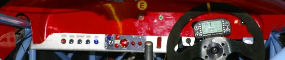
Back to the DL1…. I’m very impressed with this  little “batwing” mount  Duncan made.  He really is fantastic at visualising this sort of stuff.   It holds the DL1 safely and securely and also keeps it off the floor in a well protected almost water proof part of the car, while still allowing access to insert/remove the memory card.  We wanted it off the floor, as we’ve been working very hard to try and make sure that the car can take passengers easily, with out all the normal stuff that tends to litter the passenger space. There are  only the brake lines running on the passenger space central chassis tube.
 To this end  we’ve also mounted the extinguisher outside the main passenger space, in the area of the footwell that is beyond the diagonal reinforcing chassis bar at the end of the footwell. You can see it in the background of this picture.  BTW the cable ties are all temporary fixing for the looms… the permananet fixings will be on on neat little mounting bases.

Talking of the floor, I’ve also run the full set of brake lines to the pedals , each corner of the car is now adorned with a coiled up loop of brake hose which is awaiting the hanging of the suspension and callipers…. which should now be  very soon on the horizon as Andy is now soon to receive the new uprights and suspension from his custom machine shop.  So the brakes are now just lacking the uprights, disks, pads and fluid…. all of which I have pending the arrival of the parts.

The last piece of the wiring is the dash warning lights. With the shift lights and all the instrumentation on the steering wheel, and illuminated switches acting as self contained warning lights for main beam etc the only things left to mount are indicator tell tales, oil pressure warning ,  Neutral indicator and fire extinguisher button.   These are now fitted to the dash, and I just need to wire up this sub loom.   The lower dash edge  needs trimming, but I can’t do that accurately until I get the rest of the bodywork, and I think I’ll make a little Ali or Carbon plate to cover up the hole from the previous owner’s paddle shift.


The next thing to report is that I’ve made the seat,  we did this in the usual cast foam method using two part expanding foam.  This is a well documented but humorous process which essential entails you cooking your nadgers in the middle of an exothermic reaction with only a thin layer of plastic preventing you from being permanently stuck into the car.  True to form we cocked up the first effort, but we now have a 80% formed seat, ready for trimming.   Incidentally the orange plastic is a survival or bivvy bag.  £2 quid from ebay   we used several of these are they are the perfect option, being both large enough to form a seat in one go, and made of 500 grade plastic to help prevent “leakage”.   The orange also goes perfectly with the blue powder coat, and calls to mind the old “Gulf Racing” colours from the seventies.

With the seat in place I could now finalise, and trim  down the steering column.  This I then TIGed together, painted and fitted to the car to complete the majority of this system.

So I think I’m almost at the limit of what I can achieve inside the tub.   I need the body and floors to finalise the oil and water circuits, and finish the exhaust.  The fuel tank is ready to fit, I’m just waiting on delivery of some insulation and a new pump to replace the “Known good working” one I bought from ebay which turned out to be “Known to be totally buggered”. grrrr

 Then its time to hang the corners, the uprights, disks and brakes…. all of which I’m hoping to get from Andy soon, and which should with a bit of luck simply be a bolt together job.

Then there’s ARBs, + Dampers and pushrods, + pedals and body work fitting, so  I have to admit I’m beginning to think I’m not going to make Anglesey.

Talking of suspension that reminds me.  I’ve mounted the bell cranks & bearing packs.  These are made of 10 different components, including bearing races, ground and matched tubes + surfaces, shims and the billet bellcrank  unit itself.   Once they are all packed with grease and shimmed into place they spin like helicopters on the chassis mounts, with no detectable lateral play.


Like I said …. much to report.   Next on my to-do list is finalise pedals, finish tidying cabling, fit fuel tank and mount diff.  Then I’ve run out of stuff to do until I get the remaining billet and body from Andy…. which should hopefully arrive this week.


Posted in AB Performance Sabre | Leave a comment

Progress, Progress, Progress

Whenever I’m building a racer, I always try to work in complete systems wherever possible,  because its easier to know that for example the brakes are done rather than, I’ve done this and I’ve done that but neither is finished.

However today we broke that rule.  We got on with so much stuff that, and covered an awful lot of ground that it wasn’t possible to work in complete systems, not least because I haven’t yet got any of the suspension hubs or uprights.

First up …. brakes.  The big pile of bits that arrived during the week were mainly all brakes and fuel bits, so I set too at the front of the car and started mounting up the brakes.

This required me to a make up the central ali plate, and the mounting angle bracket for the master cylinder reservoirs.  The reservoirs are connected by -4 fittings and banjo bolts to the master cylinder inlets.   I got these from Rally Design as a fairly reasonably prices pre assembled part.  Clearly the feed lines are much too long, but for the price of a couple of  50p olives the fittings can be dis-assembled, the excess  tube cut away and the joints remade.  Unfortunately I don’t have any of the -4 olives, so this will have to be a job for next week.  I wouldn’t normally use the braided hose to feed the master cylinders but in this case I was forced too.  If you look at the feeds into the master cylinders you can see that they are extremely close to the chassis rail, so much so that only banjo fittings  will work and these are generally only  available for braided -3 or -4 hoses.

So on with the master cylinders, I needed to drill the floor mounts, and the pedals are bolted through from below.  Here you can see them all mounted up with the new pedal in place too.   The master cylinders are 0.625 inches and 0.70.   I found this worked extremely well on the Genesis which used calipers of the same piston size, and Andy confirmed that this was what he also used.

I’ve mounted the master cylinders on the “outside” of the mounting frame,  I would prefer to mount them inside the frame so that the mounting bolts are only holding them in place rather than transmitting the force,  but to be honest I’ve compromised this to allow for ease of fitting and re fitting of the components.

Also in this picture you can see the banjo fittings, the front uses a double banjo, and the rear brake circuit is a single, it will split int a T piece below the diff carrier at the rear.  The front master cylinder is also fitted with the brake light actuator pressure switch.  What’s not obvious in this photo, is the same problem I had on the Genesis in that the master cylinder push rods are too short to have a reasonable length into the bias bar clevis, and have the pedal in the correct position.   I don’t think wilwood make extension/ over long push rods… so I’ll have to make some extensions from hex bar.

While I was working away at the front of the car Duncan, was finishing the main firewall ,riveting it in place and sealing it.   While he was at it he also sealed around the engine bay chassis members in attempt to prevent any oil spillage from seeping under the rails and ending up in the drivers space.  


While Duncan was doing all the tin bashing, I got on with a couple of odds and sods like bolting up the steering column bearings, fitting the gearshift mount and fitting the main steering rack.

With the main firewall complete, it was time to refit the engine.  

Part of the preparation for this was to fit the oil takeoff adapter that I had got from Tony Guant  a fellow RGB racer, and acknowledged expert on the ZX10 engine installation. 

The adapter is to allow the oil to flow to the external cooler. The beautifully made, adapter plate, replaces the original Kwaka oil/water heat exchanger on the back of the engine, and also has the beneficial effect of simplifying the water circuit pipework.

Tony has had the adapter plate made up, as part of a batch for his own ZX10 powered Wolfe RGB racercar, and sold one on to me.

However we have a rather significant problem.   In the photo above you can see the 1/2 Bsp thread in the upper outlet, and that the exhaust is extremely close,  so close in fact that it is  impossible to fit the oil fitting at all.  It seems Tony’s exhaust layout is different to mine, and I’m going to have to do some hard thinking.  The adapter can’t be rotated as it only fits to the engine block one way. My first thought is to plug this hole using a steel threaded and tapered BSP plug, and machine the face that’s away from the exhaust to take the oil fitting.   But I do need to ruminate on it a bit more. 

Just before we permanently re-fit the engine we remember to reorient the sump reservoir so that the drain plug isn’t baulked by a chassis rail, and we also cut an access hole in the floor of the engine bay to facilitate draining the oil without removing the floor.   With this completed we refitted the engine.  This took a couple of hours, as  the new powder coat has closed up some of the clearances, and every now and then we have to stop and back track in order to clear the powder coated threads of a few mounting holes.  But eventually it’s all done up tight and the engine is properly nailed in again… Which is a major step forward.

Coo things are really moving on a-pace today.   With the clock clicking around to 6 oclock, Duncan needs to get off, but I have just one more-thing that I want to complete today….. the majority of the fuel system. 

 Andy has supplied a fuel tank, which is already fitted with a mounting plate for a CBR1000rr fuel pump.  

 I’ve checked the ZX10 and CBR workshop manuals and the pressure and flow rates of both pumps are comparable, or at least comparable enough to allow any differences to be mapped away using a Power Commander, so I see no reason not to use this tank.  I acquired a fuel pump from Ebay, and fitted it up.

Also in this picture you can see the AN -6 fittings I usually use for the fuel injection hose.  In this case I’ve used nylon braid covered hose rather than the heavier stainless steel braided version. 

You can see that the hose is entirely in free space, with no possibility of chafe-ing.  On the right is the fuel filter, which is mounted on some nylon cable tied fittings, and then the curved fitting that will flow up to the fuel rail.  The pump outlet is 12mm banjo fitting on a M12 x 1.25 x 25mm long.  I’m currently in two minds as to whether or not I should fit the MSA mandated fuel sampling valve… nobody else in club motorsport seems to bother, but I actually thing it could prove very useful for emptying the tank… which is an important consideration as the tank is in the engine bay, and you really don’t want to be sloshing fuel around too much.

With that, my feet and hands hurt quite a bit so I called it a day, but we’ve got a huge amount done and transformed the Sabre from a bare chassis to probably a 50% complete race car. More importantly with the engine in place I can now start sorting, wiring, oil and water circuits and the control inputs and logger outputs.   Hmmm that’s quite a list perhaps its a 30% complete racecar.

Posted in AB Performance Sabre, Brakes, engine mounts | 7 Comments

Double Isolation

Excuse the horrible pun, but today Duncan and I made significant progress, on two major components.  The first is the electrical isolator and its associated wiring, that kills the whole car power supply, and the  second is the main bulkhead /firewall which isolates the driver from the engine bay. 

But before I get into the detail of that, I should announce that I’ve joined the twittering masses in the tweetomatic-o-sphere.  My plan is to keep you up to date with the small updates on the Sabre and the mini, using my twitter account  so follow me @RGBracer  using the button on the right.   Thanks must go to my old RGB buddy, Stuart Tanton (if you’re a die hard reader  from way back you might remember him making a sudden appearance at the end of  this movie).  Stuart had registered RGBracer on Twitter, but as he wasn’t activily using it, he graciously passed it to me.  Stuart is currently “between cars”, but I hope he’ll be back in the RGB paddock soon.

Anyway back to the Sabre.    This was the first full day since, we got the  Sabre back from Powder coat, and coincidentally also a RGB race meeting at Brands Hatch.  Another meeting that we’re not at… so a little added impetus to get this beastie built.  So we really cracked on.

As usual we adopted our normal distribution of labour, where we each play to our strengths.  I got on with the the wiring and power supply,  Duncan got on with fabricating the firewall.  He’s way better at visualising stuff, and then making it and is an old school “measure twice and cut once” type of guy who cut his teeth building clinker built boats.  Whereas I’m a logical thinker, who is very happy with circuit diagrams, but generally somewhat ham fisted. (All very typical traits considering I’m an IT Director).

Anyway I spent the day making this little collection of parts and bits.

At the base is the new Shorai battery that weighs all of 700grams, sitting in a little foam lined ali tray, to the left are the main power relays which switch on the engine starter, and reverse motors.  Also on this ali plate are the main system fuses, one which services all the ignition circuits, and the other which serves everything else.   Lastly on the right hand side is the Cartek Isolator.  I know Tim is pretty anti this little device, but what you see in this picture is the sum total of the high current battery cables in the entire car (excepting the drive cables to the motors which will also be ultra short).   BTW the neutral line is marked with yellow flashes to comply with the blue book regulation.   I think the idea is that in extremis,  the marshals  can cut it with bolt cutters and isolate the entire car.

I’m pleased to report that all of this worked perfectly, and it powered up the main fusebox properly, when I hit the start button the start relay fired, as did the reverse, as did the fuel pump one…. so the circuits that I’d installed so far all work fine :-) and prompted a Dr Frankenstein tweet “  IT LIVES!”   I’m going to crack on with the remainder of the car systems, before I put the engine in next week or so.  One of the key areas is to decide is to layout the auxiliary switchgear, as I’m currently torn between using the bike control switches for things like lights and indicators… or fabricating my own panel.   the former gives you a lot of lightweight switches in a small package, but is just a bit low rent.  It is  what I used in the Genesis though.  Its one of a number of key ergonomic arrangements that requiren me to mould the seat very soon.

Duncan by contrast, got on with installing the main firewall.  We decided to make this in two parts, with the passenger side permananetly fixed with sealant and rivets, and the drivers side de-mountable  to allow access to the exhaust headers and oil filter.   I’ll still need to seal it, in order to comply with the blue requirements for a complete firewall… but access to the headers seems to be a very good idea, particularly as the floor plate is permanently fixed  to the engine bay.

What are now the seatback panels actually drop down behnd the chassis rail at the base to help ensure that any fluids shed by the engine,   like an oil leak, don’t find their way into the cockpit.  I’ll  also be sealing the engine bay tubes to the floor pan to help prevent leakage forwards.   If you blow up this picture, you’ll notice how neat the lines are, how consistent the fitting around the welds, and the nice neat lines of equidistant spaced rivet/bolt holes.   All of which is typical of Duncan’s work on panels.  At the end of the day, we were nearly done…. I’ve just got a few more Rivnuts to set, and some firewall sealant to get and I can get on with deburring and finishing  all this off. 

Incidentally the sides are coverd by a thin, lightweight  GRP panel, which I need to collect from Andy next week.  Judging by the way the cockpit is filling up with swarf I also need to get a new garage vac/hoover. Also on the purchasing list is a full set of brake lines and master cylinders and vast number of button head bolts,and other sundry fixings for the main components.

Also I’ve ground off the powder coat and welded the invetiable joint that we missed.  no pictures as welding a fformer  powder coated joint inevitable resulted in something particularly ugly :-( .  Still at least the cellulose paint I got is a close match to the powdercoat.

Posted in 1275GT mini, AB Performance Sabre | Leave a comment

The Sabre is back from Powder Coating :-)

Duncan and I picked up the Sabre from the powder coating folks as Fentec this morning.  She looks resplendent in her new RAL 5024 blue and I have to say I’m really pleased with the colour. Its towards the greyish end of light blue, a lot like RAF blue.   So once we got her home… and again it was in the rain, we gave her a good wipedown  and set about fitting the floor.


Of course as you wipe her down you notice the imperfections,  the odd bit of weld spatter or pin hole that you never managed to spot, or the odd inclusion in the powder coat..   Which makes you grind your teeth a bit…. but hey, the finish is generally very good, considering the rusty state she was when she went off  and  as Duncan always says  “It’s a race car”.


The powder coating guys also did a varied collection of bits, including 4 engine mounts, a chassis member, the reverse mount and two pedals.  I elected not to send the brake pedal as I didn’t fancy cleaning the powder coat off the main bearing tube…. Of course it only occurred to me afterwards that what I should have done, was cap the ends of the tube and get it coated anyway.    Still that can happen later as I’m sure I’ll have one or two bits more to be coated in the future. .

So with the garage swept clean of the worst of the crap from the “dirty, gritty, weldy” half of the build we inverted the chassis and  drilled the 300 odd holes for the rivets.  Tim had lent me some cleco’s which came into good effect to keep it all aligned, and we then removed the floor and set about deburring all the holes.  Andy recommended that I epoxy the floor panel on, and I had previously acquired some 3M 9323 B/A structural epoxy.  Quite the most expensive glue I’ve ever bought at <cough> 90 +quid per litre… but you’ve got to love a glue called “Scotch weld”. So we abraded the mating surfaces and slapped some on in fact you san see it near the floor in the picture below…. its the pink line between the chassis member and floor.   Then we set about the 300 rivets with an air riveter.  A couple of hours later and after some acetone fueled cleanup we had the basis of a race car .  The chassis was coated and panelled, mounted on trestles and we are good to start bolting stuff permanently on.   I’ts time to properly start this build :-)

So it was time to start permanently bolting on all the stuff that had formed part of the previous build activities and first up was the fuse box.  This is partially populated with the main power loom and busbars. and I now needed to fit it in place, so that I can run the rest of the circuits.  So two M5 rivnets, and a slap of the left over adhesive to help them grip, meant that it was mounted nicely on the upper chassis rails. Andy assures me that on the the Sabre this area stays bone dry, and come to think of it one of the the things I hadn’t noticed, or at least had noticed but not registerd is that when ever I see the Sabres… even just after racing, they appear not to be full of tyre debris like my old Genesis was…. this has got to be a good sign that the wheel wells are isolated from the cockpit …. and I might even keep my feet dry.  Either way I wanted the fuse box at this location, because its easily accessible and viewable here, and also because I’m trying to keep the passenger space free of as many trailing wires and cables as possible.    I want it to be very neat in this respect as I expect to be giving joy rides to my Son and Daughter and thier friends at some stage,  and of course Duncan is owed a few turns around the track for all his help over the years.

The fuse box of course needs a power supply, and at the other end is the main electrical Isolator.  This needs to be mounted on three clean studs, as it forms and switches the main chassis earth, and this was mounted up in the engine bay, close to the battery position.   Tomorrow I expect to get the battery tray, battery and main fuses mounted.


Posted in AB Performance Sabre | 3 Comments