Non-testing @ Snetterton

Ok, I last posted a couple of weeks ago in the run up to a planned test day at Snetterton on Tuesday 23rd October so that I had a fighting chance of turning up at the Birkett with at least a partially proven car .  The car was mostly complete, but lots of little things needed finishing off, and some fairly major things were missing too.  Consequently I’ve spent most of the last couple of weeks in the garage, so the first thing I must do  here is to say “Thank you” to my wife Kate for her forbearance for the hundred or so hours I’ve spent in the garage over the last few days.

So Duncan and I have  basically been spannering manically  for every waking minute of the last fortnight when we weren’t at work.  Plus I’ve had four days off work in an attempt to get ready.

Consequently, I’ve not taken many photos… but I’ll remedy that with a full walk around the now complete car in the next post or two.

To be honest it  has all blurred together a bit but over the last week or so and exhaustion levels have been high, but the summary(culled mainly from my build notes and facebook posts) is as follows

  • Front floor + frame fitted  & cut to shape.
  • Front towing eye fabricated and fitted to frame.
  • Rear body work support frame fabricated and fitted.
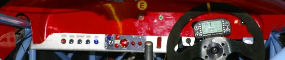
  • Dash, completed, wiring tidied up and sorted out.
  • Engine bay cover fitted and cutdown, quick release fasteners fitted
  • Foam seat made and covered, harnesses fitted.
  • Drive shafts fitted. new CV boots and one joint rebuilt.
  • Rear lights and wiring fitted.
  • Front and rear suspension + ARBs completed.

Of this little lot, the drive shafts  bear some additional coverage.  The drive shafts have standard motorsport outboard GKN Lobro joints, and inboard plunging ones.   Andy Bates over at AB Performance, had been waiting for GKN to supply a complete new set for me, and they had failed to come through in time, so in extremis Andy supplied me with his pre existing set… these had also been sent to GKN so they could use them as a pattern, and they arrived back in the nick of time on the Friday before the Snetterton test.  So that  evening I set about fitting them up.  However it quickly became apparent that all was not well.

Firstly the rubber boots were all nicked and cut and leaking grease, and one of the joints felt very odd when I manipulated the joint, so as I needed to replace the boots anyway,  I disassembled the joint.   What I found was that instead of all the drive balls inside the joint being correctly positioned inside the internal cage, four of them were simply sitting in the bottom of the drive cup.  Additionally the outside pressing of the joint was all marked and mis-shapen, with what looked like screwdriver marks.   The joint itself showed no signs of mechanical failure, overheating or excessive wear, so I concluded that it had simply been inexpertly disassembled (probably by GKN when they were measuring to make Andy his new ones).

So as I was now out of time to get an OEM replacement, and having been burned with cheesy after market crap before ( You may remember my 2010 Birkett was curtailed when a brand new after market joint failed after two laps)  I rebuilt it….It took two hours to get it back together, repacked with grease and the new CV boot fitted.   After which the other joint took 20 minutes to change the boot on, and thankfully it was mechanically unsullied,  and that was Friday night concluded.  I’d fit the joints first thing on Saturday.  For my own records the CV boots are Shaftec BK55s.

On Saturday, we got on with the front floor, and Duncan hobbled his way around fitting, cutting  and screwing it down to the correct profile.  I busied my self at the back of the car, and got the rear panel and lights fitted, along with the necessary support frame to hold it all up.    On top of this goes the engine cover which I also fitted.

Andy has used little m6 captive aerospace “nut plates” for all his fasteners on every body panel, and each  corresponding part is fitted with a countersunk aluminium bobbin to spread the fastener loads into the GRP.

This is a good idea as it helps stop the fasteners from pulling out, but it does mean you either have to use countersunk cap bolts with a small hex drive or countersunk machine screws with a pozidrive fitting, neither of which are particularly quick to remove without the aid of a small battery drill/driver and both also tend to “round off” making removal very difficult.  Besides on things like engine covers or damper access panels, you want them to be removable and replaceable without tools, and so 1/4 turn fasteners are my choice, preferable with a finger operated D ring.   For the rest of the panels, at the moment, I standardised on Posidrive machine screws (I’ll swap them out for Dzus fasteners later) .. but for the engine cover we used 1/4 turn panex fasteners.  This necessitating carefully drilling out the mounting bobbin to accept the larger shank of the fastener, and a clearance recess on the inside to allow it to be withdrawn from the substrate panel

Once I’d finished that, Duncan had finished the front floor, so we set about fitting the front towing eye.  The Genesis always had a problem with towing because the all encompassing bodywork, meant I’d had to use a strop type of tow eye (basically a webbing loop bolted to a nearby chassis member), which was accessible through a small hole in the front bodywork covered by a number plate.  But what this means in practice is that when the tow is off centre, the strop tended to pull through the body work to match the line of tension, thus tearing up any pretty GRP that got in the way in the process.   Having had this happen more than once after I’d arrived in a gravel trap, we resolved to build a proper rigid eye on the Sabre that protruded through the front bodywork, like those on Radicals do. And which could be side loaded without destroying the GRP nose.  Here it is, hewn,  mostly by hand from 4mm steel….. do you think it is ever so slightly over engineered?   And that was mainly that for Saturday.

Sunday was more of the same, the feature event was however Duncan’s 4th or 5th attempt to stick me into a racing car using two part expanding foam.   The seat we’d made a couple of weeks ago turned out to be wrong,  due to a lack of centre constriction, I’d sat too centrally in the car and the knee/arse/pedal angles were all wrong. So we started again, but this time with a central barrier made out of a spare lump of ply from the front floor holding me properly on the drivers side.

I was sitting pretty surrounded by bright orange  emergency Bivvy Bags, within which was some pleasantly warm 2 part foam just about finishing its curing process and gently cooking my nether regions, when Tim turned up to help me align the car.

Tim is a whiz at all things suspension, but him, me and Duncan did spend 45 minutes having a three way argument about how you setup a pushrod suspension system, which was moderately entertaining.  Eventually having decided that the important is to first set first  the bell crank angle, as this dictates the damper’s position in its travel, and hence the relative amount of travel available in bump and droop (we went for a 1/3:2/3 ratio Droop:bump). It also specifies  where the suspension is on the rising rate curve and allows the actual ride height to be modified using the pushrods.   Lastly we knew that it would also indirectly specify the suspension frequency by setting the spring seat position, once we sat the car back on its wheels and wound the spring seats up to return the bell cranks to their specified position.  The purists might argue to set the frequency first and then work in the sequence, bell crank, droop/bump ratio/ride height & push rods…. but this sequence worked reliably and repeat-ably for us.  The first step was to remove the springs and work out the totally damper travel available, so we could work out the droop/bump travel.

We cracked on and about two hours later the car was properly setup from a damper  & pushrod  point of view.  Of it wasn’t without challenges and course we established the rear pushrods were a shade too long, so these had to have 5mm spun of each end in the lathe.

The magic number both front and back was 200mm between the lower damper housing, and the nearest edge of the upper damper spring seat. We set the car up level… 85mm at the front Datum, 85mm at the rear, 2mm front toe out, a smidge of rear toe in and 250lb springs all around.

Lastly Tim and I set the car’s alignment parameters.   2mm toe out at the front, and just a tiny smidgen of toe in at the rear.  Oddly the car was much easier to push once we dialled out the 25mm of toe in that I had built it with :-) .   I had intended to build some alignment bars that could be bolted to the front and rear of the car, and allow string lines to be fitted perfectly parallel to the centre line of the car, and thus allow toe out to be specified simply by measuring the gap at each side of each wheel, but alas no time for that.  With that Tim left  with my thanks, and I cracked on with the last few odds and sods.

Covering the seat in duct tape, fitting the front light covers, fitting mirrors, fitting the harness eyes and harnesses and so on. Which took me until about 11pm on Monday night and then until 9:30 am on Tuesday morning.  The day of the Snetterton  test   (although I did get some sleep).

I had hoped beyond hope to get the front ARB bearings from the suppliers on Monday, but  alas no, so in the end I knocked up a couple of Ali spacers first thing in the morning and fully assembled the front ARB system for the first time. You can see the large spacer at the  upper right corner of this picture, which allowed me to use the standard Sabre ARB on my prototype chassis.  And with that it was time to dress her up and take her to the track for the first time.

Of course the first time you load a new car on the trailer you also have a learning experience .. will it fit? How do you lash it down? .. Will the shiny new winch work…etc.  By the time I was done, and the Winnebago and racer were fuelled up ,and the tools and car loaded it was 10:30 and I’d missed the morning of the test or would by the time I got there.  Still no matter it is an Open Pit Lane day, so I could still get some solid running in and shake down the car.

Now the bad news, Tuesday was foggy, and I had a call from Andy when I was about half way there to say the test day had been cancelled, and that no one had turned a wheel in the morning due to fog.   If I didn’t attend I could get a refund, but if I turned up and  and it cleared enough to do two  laps –  no refunds.  So I opted out, as the prevailing advice at the circuit was unofficially – “Not much chance… but who knows”.

Sitting in the Layby on the way, before finally deciding to abandon the day I came to the conclusion that it was probably a blessing as after 4 extra long days and multiple evenings trying to get this thing finished I probably wasn’t in any condition to drive at the track anyway.  A mate of mine totalled his new car on a test day, by accidentally changing up when heading towards the Druids hairpin at Brands…. when he should have hit the brakes.  He put that down to brain exhaustion and I didn’t want to go that way.

Alas that means I was taking an unproven car to the Birkett, with no running, and no testing …. no the best of situations, and something I’d been working  incredibly hard to avoid.

To add insult to injury I found out 3 days later that they did indeed run for most of the afternoon after the fog miraculously cleared. Arse!  It wouldhave made me any less exhausted though.


Posted in AB Performance Sabre, Suspension | Leave a comment

Front Coming Together Now :-)

My Garage normally smells of paint, welding, hot metal, hot oil, petrol, thinners and brake fluid…. in fact looking at that list it is amazing that I haven’t set fire to my self more than just the three times so far.  Today however there was a new smell… wood and woodworking.

The wood is the 6mm plywood for the front floor. I’ve been working towards finalising the front end of the car for sometime.

Here you can see the front frame, which also doubles as a crash structure and, erm triples as the mounting for the front towing eye.  Duncan started this on Saturday, by laying out the lower frame., and I concluded it today by building up the diagonal and top connections.  Also in this picture you can see the transverse Ali bar which links the lower front wish bone mounts and puts them in double shear.   This just needs a couple of additional spacers to complete it.

If you stare at the the connections you can see that they are demountable with quick release pins and clevises.  This is so that I can remove the front of the car, easily and therefore get it in my garage.

The frame has been constructed  to ensure that the floor is flat and planar with the main car floor, it just now needs some little mounting tags to hold the actual floor on to it.

The floor itself  should have been 6mm ply… except that the 6mm ply that arrived, was actually 8mm, and as a consequence was too thick to fit between the floor of the main body, and the mounting frame.  So I spent a “pleasurable” hour or two cutting some 3mm pockets in the under side to allow the main ali floor  to fit flush with the ply underneath, and give enough clearance above.  I’ll fit some slide latches to link the ply  with the the ali floors.

The whole point of fitting the frame & floor, is to allow me to mount the front bodywork and nose cone.  I ran out of time to get this finished today, but I did manage to get a couple of trial fittings done, and its all looking good.  To finish off the floor it needs

  • To be fixed to the frame
  • A transverse stiffener
  • Tension wires to control the extreme corners
  • Tthe mounting plates for the connection to the bodywork
  • and of course the front towing eye.


OK so that was Sunday.   On Saturday I focussed mainly on the front suspension.  In fact, If I’m honest I focussed mainly on the lathe, as I had to produce what seemed like 50 spacers & top hats to fit the various ends of the two dampers, two bellcranks and two pushrods.

All of which were oil blacked in the normal way.   The other thing I did at the front was to cut down and re drill the aluminium damper supporting triangles that appear on the top right of the picture. These are normally beautifully CNC made to simply bolt on the chassis, but because my chassis was built for different dampers, they needed to be rewelded, redrilled and cut down a bit… so now  they aren’t  quite so beautiful .. but they are functional.

You can also see the extended damper eyes to add damper travel without binding.  What is less obvious is that new bell cranks were welded up and fitted to add clearance for the damper eyes..   The front suspension is now complete bar the ARB connections, but as with the rear I may need to make new pushrods when we come to setup the car next weekend

Which is great as I now have 8 days until the first outing and the car is not yet ready.


Posted in AB Performance Sabre | Leave a comment

Rear Suspension Complete

Hurrah,  one end of the car is complete.

I thought I’d post a of picture of what I’ve been up to this week.

Basically I’ve been building the rear anti roll bar links and spacers.  The Links are turn buckles with LH and RH threads at each end to allow for adjustment.  The Bar ends are M6, and the damper ends are M8 because that is the bolt size that goes through the damper.  At the damper end you can see some conical Ali spacers that I spun up on the lathe. These stand off the link far enough from the bell crank to clear the springs, and hopefully are wide enough at the base to ensure no undue flex due to the stand off distance.

Overall the clearances are tight, but the ARBs have a good 50mm of adjustment on the bars, and I’ve removed the springs and run it through its full range of movement and it all seems fine.  Now onwards and upwards to the front ones, which should be much easier to make, as the clearances are nowhere near as tight.

You might notice that the ARB itself has some bends in the actuating arms.  Andy supplied the bar with straight end levers.  I had to adjust the bar using a big vice, a long lever and some brute force and ignorance, in order to make sure the  link rods clear the damper bases throughout their range of motion, and with the link ends at the lower limit of their adjustment.

There is only question remaining at this end of the car.  At full droop the wheels just foul the bodywork.  This may be because the movement of the bell cranks now means that the push rods are slightly too long even though I have adjusted them to be as short as possible (remember the push rods control ride height at full droop). I’ll check this out once the car is complete as part of the suspension setup, and if necessary either trim the existing ones  or knock up a couple of new ones.  I have the bits so it wont take long…. which is good as I now have about 12 days before the first test.

Posted in AB Performance Sabre, Suspension | Leave a comment

Body & Suspension

OK, we’re making good progress now, as we move to the end game.   First up bodywork.  I had picked up the remaining mounting plinth for the right hand side pod last week, and Duncan (and his duff knee) spent most of this Saturday fitting it.    Firstly the plinth is mounted to the side pod, and bonded in place with a bunch of divergent rivets and some polyurethane sealant (Tiger seal or CT1).   The body itself sits on top of the plinth is mounted with M6 captive nut plates, and some M6 countersunk set screws.   Ultimately I’ll probably change these for Dzus fasteners, but for now the screw fasteners will be fine, as I’m not expecting to remove the sidepods very often. Obviously fitting the fibreglass, tends to be a lot more time consuming with a fair amount fit/refit/trim activity and a fair bit of groaning from he of the crocked knee.   But Duncan did a sterling job, and I can now report that both sides of the central tub, are complete and fitted, along with the internal shrouding that guides the air through to the oil and water radiators.   This is a crucial step as all the other bodywork is keyed off these items.   This of course includes the dash\scuttle section, which we can now trim to it’s final size.

As for me, I spent most of Saturday finalising the rear suspension.  Andy has supplied me with the front and rear roll bars, so I got on with finalising the rear suspension setup.    Now you may recall that I had previously mounted up the suspension, and it looked like this. This installation has a number of issues, all of which I’m sure are related to the fact this this is a prototype chassis.  It’s not a problem, and exactly was I was expecting. If I tell you that the suspension is on full drop because the car is on jacks , you may start  to see the  problem. At full droop the motion of the suspension is limited by the maximum damper extension, that’s what stops the wheels falling closer to the ground.  So that is the situation here. Now if you look at the bell crank, you can see that relative to the input from the push rod at bottom right of the picture, the bell crank  pivot that connects to the damper (The silver bolt at the top of the crank) is already past the centre line of its circle of rotation.   This means that as the push rod moves up from the full droop position it has limited travel, before the push rod impacts the silver centre aluminium hub of the bell crank.  This will be the upper limit of travel,  and is the effective full bump position. In practice you want full bump to be limited by a nice rubber bump stop, which prevent metal on metal contracts.  I’m very concerned that this current arrangement would quickly destroy itself, as its motion limits are bits of metal banging into each other.

The positive outcome from this arrangement is that the suspension is rising rate.  ie the spring appears to get stiffer as the wheel deflection increases due to the rotation of the bell crank and the relative angles of the motion inputs and outputs…. which is a good and desirable thing as it stops the suspension collapsing under load.   But, the arrangement as delivered, limited the overall wheel and damper travel to about 40mm, before it all locked solid.  While this is acceptable on a formula 1 car with massive amounts of  down force and huge tyres, where much of the springing medium comes from tyre wall squish.   It’s not desirable in RGB where we have minimal down force, and the relative weight of the car is low… so the tyre walls don’t get squished too much.   In other words rather than using the tyre walls as the major part of the spring medium like F1, I need proper old fashioned suspension that uses the springs, and if I need proper suspension, I need the damper to move through a much larger stroke to control the motion of that suspension.  Why?   Because dampers work by controlling oil flowing under pressure through an accurately sized orifice or valve and it’s almost impossible to control a very small amount of fluid under high pressure accurately.  Think of a garden hose, kink the end so there is no water flowing, if you you turn on the tap and set the pressure high, it is incredibly difficult to release a controlled  very small amount of fluid, by controlling the hole size at the exit.  Conversely if you set the pressure lower, its much easier to control the flow of a larger amount of fluid over a longer length of flow by simply controlling the orifice size.

What I’m trying to say is short suspension travel, and limited damper movement may be good for a formula style car with slicks and wings… but I don’t think it will work for an RGB car with limited down force.  RGB cars rely much more heavily on the mechanical grip of the tyre contact patch, and maintaining the contact patch requires a longer damper stroke so the dampers work correctly, and a longer suspension travel to handle surface changes.

So after much consultation with Tim, we came up with this arrangement (this is the left rear wheel, above is the right rear version).

The intention is to increase the available damper travel, so the valves work correctly, and also as a consequence gain addition overall suspension movement. Firstly you can see we’ve turned the rear (rightmost) damper mount around to move the damper forwards in the car. You can also see that I’ve pocketed the profile of the bell crank so that it doesn’t foul on the damper body.  (this picture was taken at approximate normal ride height rather than full droop), so at full droop the bell crank will rotate at bit further anticlockwise.

Initially we altered the shape with a flap wheel in  an angle grinder by trial and error, but once we had the profile, I drew it up in my CAD software, and had the new plates laser cut by Peterborough laser cutting.  So I spent some time on Saturday welding up the new bell cranks together, and painting it all. You can now see that even at ride height (which this picture is taken at) the bell crank hasn’t yet got close to the centre line of its rotation.  Consequently the damper will use much more of its available length, and the suspension will also have a longer travel.  The downside is that we’ve probably traded a little of the rising rate characteristics…. But frankly I’ll trade a little rising rate to ensure I have a viable suspension travel.

This damper is actually fully installed and all I need to do now at the rear is to fabricate and connect  the anti roll bar.   Here you can see the old & new bell crank profiles for the rear suspension. Ialso  had some originals made up so that I can recreate the original configuration easily if my modification and reasoning prove false. Remember I ground up the originals to find the appropriate profile so I’ll need some new ones.

The other thing we did, was to insert some 3mm laser cut spacers at the mounting points for the hub (basically cut from the same material, with the same profile and mounting holes as the low left 3 three holes in these side plates.   This had the effect of widening the gap, between both sides of the bellcrank, and resolved the problem that I had reported earlier with the dampers binding, as there is now more clearance to allow the damper eye to articulate. Of course with a much wider gap, I had to remake the Top hat spacers that centralise the in the damper and push rod eyes in the bell crank gap, and which convert the 1/2 rose joints on the dampers, and 7/16 ones  on the push rod to the 8mm bolts that fit through the holes in the plates.

And that was pretty much my Saturday… fabricate the new bell cranks above from the laser cut components and make endless top hat spacers on the lathe, before I was eventually able to bolt it all together and call it done.

Over the winter I can experiment with alternative bell crank profiles to see if I can recover some of the lost rising rate, while still retaining decent damper and suspension movement… but for now I think I have a workable arrangement for the Birkett.

I should also say thanks to Andy who supplied me with his original drawings so that I could get the bolt hole positioning extremely accurate on the new profiles plates.  Incidentally, These issues are to be expected because my chassis is a prototype chassis and therefore different from the production AB Performance Sabres.   If you bought one, your suspension would just bolt on, and you’d get brilliant support from Andy throughout the build, as I have done.  These issues are simply because this chassis was originally built (we think) for different dampers.

Now on to the front.

Handily the front dampers are located side by side so its easy to do a direct comparison.

Again this picture is taken at full droop, the new damper arrangements is on the left and the old arrangement is on the right.

Here again I was trying to address the issues of maximise suspension movement before the suspension locks up, and also maximise damper movement so the valves work better.

After my long winded preamble above,  I won’t cover the same old ground,  but in the new arrangement you can see the bell crank is again  rotated away from the damper to increase the available articulation of the system and hence increase available motion.   You can see the pockets in the new damper, and if you squint closely you can see that the bell crank is also much thicker due to two of the 3mm spacers I mentioned earlier.

Pro Tec have also supplied me with some extended mounting eyes to allow the LH damper to have a longer reach (but not a longer stroke), so that it could reach the rotated bell crank with out the necessity of cutting out the mounting points near the adjusters at the top of the picture and re fabricating them.

Incidentally, rotating the bell crank doesn’t affect the ride height, because one of  the beauties of push rod suspension is that ride height is controlled by the length of the push push rod, not by the position of the bell crank or spring preload.  And the push rod is made easily adjustable as it is one long turn buckle, with a LH and RH rose joint at each end, so simply releasing the locknuts and rotating the pushrod changes ride height and corner weighting, and in this case also compensates for the bell crank being rotated (assuming you don’t run out of adjust-ability on the push rod)

With push rods suspension.. The push rods control ride height and corner weight, the bell cranks control suspension rate characteristics and the suspension ratio (how much the damper moves for each mm of suspension movement) and the springs control suspension frequency, as well as the overall behaviour under load. Finally the dampers have separate controls  for controlling wheel motion in bump (the black adjuster) and rebound (the red one).

Obviously there are a vast number of adjustments to get to grips with here, and it contrasts starkly with my old car which basically had three adjustments only.  Change the springs, wind the spring base up or down or a single knob on the damper that controlled both bump and rebound in a fixed relationship.

I’m clearly in for a bit of a learning curve in setting this car up. Those first few hours testing are going to be fun!

So last major bits of the suspension are to build up the right hand front bell crank, and build both ends ARBS.   Then the suspension is done or at least ready for setup.   I’ve still not quite got enough travel on the front, so I might get a yet longer mounting eye from Pro Tec for the dampers.


Posted in AB Performance Sabre | Leave a comment

More on “The Big Push”

Here we are at the first of October, and the Birkett is now just 26 days away.  So here’s a bit more detail on the big push to get this car completed and tested in time.

Right I do have a fair bit of progress to report, and I’m starting to believe that this thing might eventually be finished.

On Friday, thanks to another day off work, I had a further 8 hours of activity to throw at the Sabre.   My focus  was to try and get the engine bay completed, so that I could close out the firewall panel which segregates the cockpit from the engine bay.

First up was the airbox. While I think I’ve found a way to incorporate the filter and intake I still needed to seal the normal input channel that feeds it in the bike installation.    This I achieved with the aid of a bit of bent aluminium, and a bead of polyurethane sealant, after first hacking off the old intake channel.

Here’s a pic of the finished part, although for all of you old enough to have been hooked on Star Wars back 1977, after queueing all the way around the building to see it  on the first day of release,  I think it looks like a star fighter helmet with the blast shield down.   I can almost hear Alec Guinness telling me to “Reach out with your feelings” when I’m fighting the hover droid in Jedi training.

With the airbox off, I also had access to the stick coils, and leads.   The previous owner had hacked in an after market ignition controller which is illegal in RGB.  So I first had to repair the coil control leads, and then change the plugs for shiny new ones.  After which  installed my power commander, and ran the earth lead down to the engine bay earth point.  The last thing under the airbox, was to block off the pair valves on top of the engine.    These bleed free air into the exhaust to help reduce emissions, and that  will completely blow any lambda readings, so normal practice is either to remove them and tap  holes in the head to plug with a  bolt… or do as I did, which is to link them together with a blocked hose.  Time is short… so I took the simple option… I’ll remove the head and tap it over the winter.  During all this work, I also managed to resolve an intermittent misfire… which was clearly a wiring/loose connection problem.

As I won’t have time to get the engine mapped before the Birkett, I think I might have to ask Bob or Tony if I can borrow one of theirs for the best race of the season.

A little bit of heat shield on the crank and cam sensor cables, and the top end of the engine was ready for final fitting.  On went the airbox, and the throttles, and at last I could attach the throttle cable. Again this was all nicely wrapped in NASA heat shielding.   This of course allowed me to finalise the throttle cable routing all the way to the pedal.  Once it was attached I couldn’t resist a few minutes sat in the car with the engine running, blipping the throttle and making her growl, just to revel in the fact that the engine is connected to my right foot :-) .   Here’s a picture of the completed engine bay… its always nice to see the heat shielding appearing, as its amongst the last things to go on so it always signals that we’re approaching the end of the build.

So after a few minutes of grinning and practising going up and down the gearbox (remember the diff isn’t currently connected to the wheels as I have no drive shafts). I shut down the engine and cracked on with the rest of the engine bay wiring and tidying up.   The last job before I could refit the firewall, was to add the exhaust wrap on the last collector of the exhaust.  This is always a nasty nasty job as the fibres get in your skin, no matter how much protection you wear, anyway after 40 mins of continuous  cursing the job was done, and the final two springs could befitted to the exhaust to complete the unit.  With that and after a general clean up and wipe around the the engine bay.  I could refit the firewall.

Refitting the firewall, also prompted me to  have a general clean up, and I’m pleased to report that the car is now looking very smart, once the 10000 rivet mandrels, cut off cable ties, and bits of wiring have been cleaned out.

The last thing I managed to finish off was all the connectors on the dash, and give it a preliminary trim. I’m just waiting to get the rest of the bodywork fitted to settle its final position, before I can take off the last 1/2 inch or so.  Included in these connections, are the external kill switch and fire extinguisher trigger… which have now been tested and passed ok.   Behind the dash, the DL1 Logger mount and cables have also all been finalised.

Hmm, when written down it doesn’t look like much.  but in in the flesh the car is looking a whole lot more finished.  Although, that’s not the final position of the extinguisher bottle, you can just see where it will end up; in the little blue tray behind the diagonal chassis member at the bottom of the passenger foot well.   The extinguisher has just returned from its service, but in the meantime I have run the feed pipes to the nozzles, and the installed the wiring.  So once I install the bottle that is another system finished.

Incidentally in this pic you can see that both the passenger and drivers footwell are nicely clear of gubbins, and so should allow me to passenger my son and daughter around the odd lap. :-)

Talking of finishing stuff,  all of the brakes  are now connected, and the system has been filed with fluid and had its first bleeding session.  I’m pleased to report no leaks. It usually takes a couple of bleeding sessions to get all the micro bubbles out of the system…. Of course now that the brake pedal is properly hard It’s immediately apparent I need to move the throttle slightly if I am to heel-toe it correctly when changing gear… but that can go quite a long way down the to-do list.  I also checked the brake light switch for correct operation… again it passed the test.

I also spent a fair bit of time aligning and checking the steering, fitting all the bolts and finalising every part of the steering system from the wheel to toe links.   Only two things remain,  I need to set the toe angles, and shim the outboard ends to prevent bump steer.  Both of which are part of the final geometry setup.

While working around the steering, I also stripped, checked and tightened the front suspension wishbones and hubs… So that is all done too. I’ll do the back once I get the drive shafts.

So I have three working pedals, a complete steering system, a complete engine installation, completed wiring system, completed exhaust, completed front hubs, completed brakes…. this thing is nearly drivable :-).

The last part of the drive train that I can actually complete, pending the arrival of the drive shafts is to fit the chain tensioners.  You can one  here.  Along with the finished, and properly mounted chain.

It looks a bit  complex, but from right to left. the components are; fixed pusher plate on the diff bearing carrier, then the cylindrical pusher which engages in the push plate. Then a lock nut and Nordlock washer. Then a captive nut that acts  on the shaft and bears against the chassis tube to apply the tension pressure.  Then, on the other side of the chassis, a second lock nut, and finally a pair of nuts locked together, pinching a washer between them.  The two nuts providing  drive to the M12 threaded rod that drives through the chassis tube using the thread in the captive nut, and the washer gives you somewhere to land your spanner on… which makes life a lot easier.  The operation is to simply to undo the two lock nuts either side of the tube and then twiddle the far left ones using a ratchet spanner, which drives the threaded section to the right and thus applies tension to the diff carrier.   Its a lot easier to use than it is to describe.

So the main things left on the two do list (apart from small stuff like towing eyes and roll cage padding) are finalise suspension build and setup, fit drive shafts, fit bodywork and lights.

Now talking of bodywork.  Duncan spent most of Saturday, fitting and fettling the left hand side pod.

As always he’s much better at that sort of stuff  than me.  I think the photo speaks for itself on the accuracy and neatness of the fit.   Just behind the number you can see the coolant radiator and shroud.  Again finalised and fitted by Duncan.  As always, having worked out how to to do the first one… the second one will as always go much quicker.

Talking of the second one,   I am just waiting on the mounting plinth,  otherwise I think we’d have had both sides done.  but as we were playing with bodywork of course we had to dress the complete car…. just for the enthusiasm boost.

This was far from an empty exercise though, as it illustrated that the filter arrangement fouls the engine cover badly, so I will have to do something else for the Birkett (I’ve simply removed the filter for the picture)… perhaps just a shaped mesh with a large sock filter.  It also proved that the car is pretty square and does fit the bodywork without too many concerns.

Of more concern is that fact that the fully dressed car is just 100mm (4″) shorter than my garage…. so I think I’m going to have to make the front bodywork and supporting bracketing and floor easily removable, if I’m going to be able to walk around the car.

Still with 3 weekends to go before Birkett and testing week…. we’re looking pretty good.


Posted in AB Performance Sabre, Brakes, dl1, driveshafts, Engine, Exhaust pipes | 2 Comments

Pedals, Intake and Extinguisher

Right.. the best (and last) race of the season, the 750MC Holly Birkett 6 Hour handicap race is about a month away, so I’ve really got to get this beastie finished, in the next 3 weeks, if I’m going to get out testing before the race.

So to that end I’ve booked Thursday and Friday off this week, in the hope that a long weekend will see all the mechanical, work done, and that I’ll just be left with body work to fit, and suspension setup to do during October. So here’s my report from day 1

This little collection of widgets are the components of my clutch pedal. The clutch has been playing on my mind for a while and having worked out the cable routing and mount, the first thing on my agenda was to finalise and install the pedal.

I’d ordered the clutch cabled from Cable-tec earlier in the week, and they turned it around in 24 hours. Which is great service… I also got them to send me a complete spare cable and couple of spare inner pull cables. So no excuses, it wa time to connect the engine to my feet.

I had been pondering for a while on how to build the pedal stop to stop the thing falling towards me under pressure from the clutch springs. Eventually I decided to build the little aluminium widget near the pivot at the bottom of the pedal. This is actually in the right orientation, but will slip between the pedal sides. The long bolt will bear down on the bolts that actually mount the pedal on the floor. It will be kept under tension by a light compression spring to stop it unwinding. You can see it in position in the photo below, along with the painted up mounting widget and the clutch cable.

This photo actually covers a few hours work, and shows the 90% completed pedal arrangement.
A bit of a sit in the car, wearing my racing boots indicates that the arrangement is is mostly right, the throttle pedal just needs thinning down a bit to stop me accidentally hitting itwhen I plant the brakes. I once ended up in the wall at the hairpin at Cadwell due to that particular fault.

Anyway you can just see the throttle cable on the right, along with the throttle return stop on the chassis member. On the left is the clutch cable and mount.   The mount has been fitted to M5 rivnuts in the chassis members. Both cables run down the sides of the footwell, well out of the way of my feet, so I’ve managed to keep the footspace clear on both sides. The clutch passes under the front of my seat, and then both cables exit to the engine  high on the right hand side of the car behind my right shoulder… all very neat :-)

You can also see that the brake adjuster cable is in place, and I can report that the the other end is connected to the dash controller knob.
In fact the brake installation is fully complete, except for the fact that the front brake lines aren’t attached to callipers… but they are all terminated and cut to length.  The back lines are all fully installed and connected so tomorrow (with a bit of luck). I’ll be able to fill the reservoirs, and bleed the system.

I’ve said that the installation is 90% complete…. this is because I can’t finally fix the clutch cable as I may need to remove it in order to thread the fire extinguisher back into its cradle on the left of the pedals, it is currently away for  its biannual inspection and refurbish at Lifeline fire systems.

The throttle pedal can’t have have the cable finalised, because I’m just finalising the air box, and that means removing the throttle bodies,which in turn, means I need to remove the throttle cable.

Over the winter I will probably mould up a bespoke airbox, but time is  short, so for now I  will be altering the standard one.  Again after a far bit of thought, I’ve come up with a solution…. hopefully a simple one.

Firstly I’ll simply blank off the front intake of the zx10 airbox, and remove the standard filter.  While I was doing this I discovered that the previous owner had removed most of the filter element anyway.

In order to feed air into the top of the box, I’ve cut a 85mm diameter hole in the top, and I’ve fitted in the red spun aluminium intake duct you can see in this picture of the inside of the airbox.   I’ve mounted it on the inside of the box, so that there are some nice radius curves to help the air enter the airbox.  It will be held in place by a liberal layer of polyurethane sealant.

Of course this means that there is no airfilter in the path. So the plan is to to fit a suitable sized conical filter to the tail of the red duct, on the outside of the airbox.

Here you can see it sitting on place on top of the airbox.  I do think it is slightly comical and has something of the dragster about it though.

It should work ok, and I can feed cold air at it fairly efficiently via a hole in the main engine bodywork.  But it is of course a stop gap before I build a proper one…. but I’m rapidly running our of time, so it will have to do.

There is one slighly concerning issue though.  Because the engine sits slightly off centre, the filter foul the bodywork, because the bodywork engine cover is symmetrical about the centre line of the car, rather than the centre line of the engine.  If that is the case then I may find a 45 degree elbow useful.

I mentioned earlier the extinguisher, well the last thing I managed to achieve today was to mount the extinguisher nozzles. The cockpit one was pretty straight forward, but the engine bay took some thinking about.
There are no clear rules or guidelines in the MSA blue book, and I have previously pointed mine at the intake + fuel side of the engine. But if the point of the extinguisher is to protect me rather than the car, then there is a reasonable argument to point it at the exhaust side of the engine. In my experience it is usually the exhaust that ignites hot oil, ejected from the engine after a failure that causes small fires, and given that this would be directly behind my back I decided to mount the engine bay extinguisher nozzle here.Tomorrow, I’m eto finish the airbox & throttle, finish the extinguisher installation, put on the chain tensioners and finalise all the stuff to do with the exhaust, so that I can close off the panel behind my behind my back. That should pretty much finish the engine installation and leave me with the suspension to finish off, before I crack on with the bodywork.

Posted in AB Performance Sabre, Brakes | Leave a comment

Coolant, Oil, Clutch and Drive

Lots of small jobs make this week’s post less than riveting  I’m afraid.  But they are all on the route to making this beast drivable.

Firstly, I’ve replaced all those silicone bends in the coolant system with some bespoke bent ali pipes that Duncan and I knocked up last weekend.  The pipe bending went fairly well considering we were learning to use a new machine, in that we only threw away two versions that we screwed up.   Unfortunately, it meant that I couldn’t mount the reverse motor at all. When we  came to complete that corner of the engine bay it transpired that the new battery, which I’d installed after deciding to ditch the ultra light but ineffective lithium one, sat about 10mm higher and clashed with the reverse mechanism. Dammit!

So we had to remake the battery mounting tray and all the large current battery cables, which dispatched the complete morning.  Once we’d finished we did have a perfectly serviceable installation, although its very tight in that corner. However, there is an air gap between every component, and especially between the hot coolant pipes and the fuel tank.  You’ll also see that I’ve also added a 50amp red Anderson connector, which will serve both as a battery charge point, and an emergency connection for my axillary ”jump” battery. Just in case the main battery has a problem mid weekend, as I’ll have to remove the entire coolant system if I need to change it it.

In this picture you can also one of the left side pod stays that Duncan also knocked up, and the car now has both side floors fitted, along with both clamshells which close out the cockpit, and suddenly it is looking much more “car like”.
Now, in the last post, you may recall that I had a problem with oil pressure readings.  The existing sensor unit was doing some really weird stuff.  In the various sessions of coolant system testing I’d even observed the oil pressure increasing as the oil temperature increased which is basically against the laws of physics, as raised temperature makes the oil thinner. So eventually I decided to swap out the ETB instruments sensor for the  Race Technology one.  Unfortunately this required more than just a sensor change as I also had to change the wiring.   The race technology sensor is a three wire sensor, whereas the ETB one is a single wire one.

Here you can see the sensors installed with the original bike low pressure switch attached to a T piece.   The great thing about the RT sensor is that it is pre calibrated within the software.  Once it was all re-configured, it all seemed pretty good until I did the main oil pressure test , which should give 28-35Psi at 400 revs with the oil at 80 degrees.  Unfortunately I could only get 25.   Hmmm

So I decided to check it even further, and installed my analog dial type fuel pressure gauge in the T Piece.  Then I had a brain wave,  despite me choosing the PSI variable in the config software, it wouldn’t be beyond the realms of possibility that it was displaying BAR without the decimal point, a quick calculation (multiply bar by 14 to get PSI) seemed the indicate it was plausible.  So I went ahead  and manually entered the PSI formula, then re flashed the Dash4Pro display.


Hurrah success!… The analog gauge and the digital system were in perfect lockstep as I wound up the revs to the necessary 4000 rpm,  and I got the perfect values when I did the 4000rpm test.    When The engine is cold I get 32-34 PSI at idle and when the oil temp is in the 80-90s I get about 4 PSI.  All of which aligns with my mates Tony and Bob, who both run ZX10s in RGB and with Andy Bate’s experience.   One way to improve pressure is to run 15w40 oil, rather than the 10w40 I usually run…. but at least I know that I’ve got main bearings in good condition and I can trust the displayed values on the dash.   Excellent.


Next on the list was installation of the drive train.  Andy is awaiting some driveshafts from GKN, but not withstanding this last link in the drive train,  She’s pretty much ready to go.

Firstly I had to remove the reverse motor sprocket, as I needed to file down and extend the  spanner flats on it  to allow me to get my largest ever spanner (34mm) onto it so that I could tighten it in the increasingly congested engine bay.  This happened easily enough, once I’d broken the grip of the threadlock holding it on.

Once that was off I swapped the front sprocket to a 17 point one. Tony Gaunt suggested the optimal choice for the zx10  for most tracks was a 17 front and 52 point rear. Which, after I had fitted the reverse gear again (more threadlock)  meant I was ready to fit the rear sprocket.

As always I use 530 sigma DID x-ring chain, and the chain in this car is 101 links long…. which is usefully just short of the 102 links of a standard size, so I only have one link to remove, and I’m not throwing away cash.   As always I get all my sprockets from B&C express, who know the bolt patterns and clearances for the Quaife ATB Diff  (QDF7ZR), and   who also supplied the chain and a natty little 60 quid chain break tool that works extremely well to remove the unwanted link.   Much better than the bash it (and your knuckles) with a hammer type I already have. While doing all this I pumped the Diff full of grease too.

Of course I also needed to cut the sprocket in half so that it will be easy to change without demounting the diff… this is just a tedious exercise in accurate hack sawing.  The sprocket is mounted using 50mm 12.8 grade Cap  head bolts, cut down to 32mm and fitted with M10 K nuts and nordlock washers,   I use over long bolts because that gives me an untreaded shank through the holes for extra strength.  This is desirable as essentially all the power of the engine goes through the shanks of these 8 bolts acting in shear.  So extra strength is good :-) .  So that’s the drive train installed, bar the tension devices,,, which are just a couple of threaded rods and nuts and those GKN driveshafts.


Duncan spent  a couple of hours making a heat shield  and support for the exhaust can… and then finally we got on to a job that’s I’ve been dreading.  Making the clutch pedal.

The reason I’ve been dreading this is that I’d originally planned, an arrangement that brought the clutch cable in to the pedal from above, so that I kept the cable away from my feet…. I want both the passenger and driver foot wells to be as clear a possible.  We’ve since decided that this is way over complex and the KISS principle should apply.  Hence the way to go is to bring the clutch cable along side my left foot  to a hard mount for the outer, and then actuate the inner cable  with a simple stand off from the pedal.

This simple little description covers about 90 minutes worth of measuring, faffing and fabricating.   All of it, of course, down by my feet, so it definitely took both of us.

The result was this natty little bracket which we will rivnut into place.   If you look carefully you can see a little angled threaded bush holding the cable outer,  is carefully angles down and  away from my feet.  This I knocked up on the lathe and then TIGged it onto that piece of angle which was hewn from some 2 x 1 box section.  Of course it would have been better to weld this all to the chassis before we powder coated it… but as they say ” hindsight is an exact  science.”

With that,  we ran out time on Saturday,  but I just now need to paint and fit this widget, and fit a return stop to stop the pedal falling towards me.  Looking at the strain on the pedal sides I also need to make a bigger centre spacer for the actuating arm.  But the monster of a job that has been sitting on my to-do list for a while has been slain …. yay :-)

Oh and does it clear my feet?   yes of course it does.  The angle of the cable and the bracket is carefully set to match the rest angle that my left foot forms when my heels are on the support bar….. I don’t even known the cable is there.  Which is great.


After Saturday tea, I festooned the kitchen table with wire, shrink wrap, cable ties and other paraphernalia so I could get on with the main dashboard.

After much clipping, soldering and shrinkwrapping I ended up with this.

The two ultra bright RED LEDs are dual oil warning lights. The greens are indicators (and are slightly larger than the LED I would have used because I (Cough) drilled the holes in the wrong place.    The green light is neutral indicator, and the red square push butting under a protective shutter is  the fire extinguisher trigger.   It’s all nice, neat, and minimalist as most of the instruments are on the DASH4PRO.  Incidentally the holes are for the previous owner’s  paddle shift actuating rods…. which I won’t be using so they will be covered with a little Ali plate.


Just for Tim  here’s a shot of the back so he can verify my wiring is up to scratch.


Posted in AB Performance Sabre, Brakes, Cooling, Data Logging, driveshafts | Leave a comment

Brakes and Cooling.

I’ve much  progress to report again today.  Which is a good thing, as while I’ve missed my target of being at the Anglesey meeting in Mid August,  I do not want to miss the Birkett at the end of October.

I’ve now hung all the suspension, so the car has been rolled out of the garage,  but this will take a full blog post on its own to cover and I need to revisit my notes to ensure it makes sense, so right now I’m going to focus on two other  major milestone systems which we’ve completed this weekend.

We’ve finished all the components of the engine bay installation and had her running :-) , and I also  have most of  a complete braking system.  We do seem to be accelerating towards completion at the moment.  :-)

Firstly lets talk about the cooling system. This is arguably complete, it’s certainly water tight, cooling the engine and has been pressure tested.   But I currently regard it as a “mock up” as its got far too many individual bends in it linked by short aluminium tube joints.   To build it took 19 jubilee clips which is far, far too many potential failure points. The jubilee clips are a bit oversized anyway so I want to change them.

So I’ll be replacing most of these silicone bends with  single lengths of 1″ aluminium tube bent to the correct shape.   I would have done it this way first, but the tool I’d ordered to do the job failed  to turn up in time. So I decided to mock it up, using silicone, and Tim kindly lent me a few spare elbows that he’d collected over the years to enable me to complete and test the system… that’s why the elbow in this view appears to have a redundant take off.  It’s because its one of those borrowed bends which will be replaced shortly.  The radiator is a double pass 400mm fully aluminium radiator that I got from ebay.   The outlets are 32mm , and its also got a little air bleed on the top right, to bleed air from the rad back to the header tank.  Its designed for a MK1/2 Golf Gti/Scirocco 1.6 1.8 8v (1986-1992).  The radiator is mounted on a little top hat section which I made,  which both raises it to the height of the aperture in the bodywork, and also usefully stiffens the left hand side pod floor.  The rad is also fitted with 4 mounting bosses on both sides, which  are handy for attaching mounting hardware too. The fan, itself is a standard 2010 zx10 fan, mounted on rivnuts in the top hat section, and a little bracket mounted on the top shroud of the rad.

This picture, basically shows all the rest of the system.
The black hose passing from the top left hand corner, under the tank, and then joining via a short aluminium section to the blue bends at the bottom of the picture is the hot top hose from the cylinder head outlet.  It flows continually down hill to the rad, and this would normally cause a problem, because any air bubble would collect in the thermostat housing/head and cause and airlock, with the inevitable overheating problems.  But, if you look in the top right hand corner you can see a pair of mole grip crimping a small pipe.   This is the airbleed from the very top of the cylinder head,  for this mockup we just bled the excess air out of the system and then crimped the hose with some mole grips, In the final installation this will connect to the bleed nozzle on the lower left of the header tank, where it will meet the blue hose (the bleed from the top of the rad) at a T union. This is an inverted loop, so any trapped air should rise up to the header tank via the T junction, it also allows the system to be filled from the lowest points, which also helps prevent airlocks.

The cold feed comes from the bottom of the rad up to a T junction, which allows connection via a 90 degree elbow or two to the header tank.  It then dives down again to the upward  angled inlet on the standard water

The only other two bits of the system are a small cap plug on the 10mm  outlet on the water pump outlook which would normally  feed the oil to water cooler on the back of the engine (which I’ve removed), and the standard block hose which feeds the water pump outlet to the head inlet.

The intention was to keep the system neat and simple, to retain a clear expansion tank, as this is both cheap and enables very quick level checking. And most importantly of all, to try and make the system self bleeding, to avoid air locks, which have been a serious problem on previous engines.

Once we’d got the system together, and checked it twice, we filled it up with plain old tapwater to test it.  We then pushed the car out of the garage, powered her up, did a few last checks  and hit the start button.

She growled into life at first thumb of the button… which was nice. And we just sat and watched her… correcting a solitary leak, and checking now and then for oil leaks or other issues.  She was a bit noisy as the PAIR valves aren’t currently connected, but it pretty uneventful  (WHICH IS GREAT :-) ).    The temperature rose gently to about 95 degrees and then the fan cut in, and the temperature then dropped slowly until the fan cut out again, which is the normal thermal hysterisis and means the Fan is correctly sized.  We let her warm up again, and then killed the ignition with the fan running.  Turning the ignition back on, restarted the fan, without starting the engine.  Again this is great, as the ECU will control the fan even if the engine is not running, so I can bring a hot car back to paddock, kill the engine, and then leave it sitting for a couple of minutes to help cool the  engine.  Of course I’ll be relying on circulation by convection, as the pump is mechanically driven by the engine, but as that is powerful enough to drive the earth’s techtonic plates… it may also work well here.   If not, I’ve got a very small bypass pump I can fit if necessary, but at this stage I’d like tot try and keep the plumbing really simple.

I will replace all those bends with purpose bent Ali tubing once my new tube bending machine arrives.

One odd thing did happen, as the engine heated up, the oil pressure dropped and dropped until it was showing an indicated zero.  I wasn’t too bothered about the particular number displayed on the Dash4 Pro as this is most likely a calibration/sensor error,  but it is certainly something that I want to investigate  further, because I really need to trust the oil pressure numbers.

So onto the brakes.  These have proven a little more problematical than  I would have liked, basically there is not much clearance at all, even with the spacers I mentioned in the previous post the wheel rotates but does just drag on the inside of the rim, periodically.   There is about 5mm of clearance between the edge of the disk and the inside of the calliper so the obvious thing to do is mount  the Powerlight callipers  further towards the centre of the wheel, so that the outer edge doesn’t rub on the rim, but still to maintain the necessary disk/caliper clearance.

The mounting brackets, have fair bit of clearance so the obvious thing is to machine back the lands where the caliper sits.  fortunately I know a mate in CAM7 who has a manual milling machine. So a quick hour spent at Steve W’s house (you can see the machining at the ends of these brackets) meant that I had some significantly thinned down brackets (about 2mm) which now mean that the callipers fit inside the wheels.   Or they would have done if  the threads hadn’t stripped out of this mounting bracket… I guess that means I’ll be learning how to helicoil the damaged threads then.


Posted in AB Performance Sabre, Brakes, Cooling | 2 Comments